Peak factor reduction device

a technology of signal processing and peak factor, which is applied in the direction of electric variable regulation, process and machine control, instruments, etc., can solve the problems of power efficiency, device size and running cost increase, and non-linear distortion outside the transmission frequency band to become a disturbing wave for other systems, so as to achieve the effect of further enhancing the peak limiting

Inactive Publication Date: 2006-02-14
HITACHI LTD
View PDF3 Cites 20 Cited by
  • Summary
  • Abstract
  • Description
  • Claims
  • Application Information

AI Technical Summary

Benefits of technology

[0015]Even when the peak limit is incomplete and the error component remains as a result of offsetting of the impulse signals in the above-described processing, the peak factor reduction devices are connected in multistage and in tandem as shown in FIG. 2, whereby the peak limiting effect can be further enhanced.

Problems solved by technology

If when transmitting a normal property signal by a radio transmitter, sufficient linearity is not secured even for large instantaneous peak amplitude, non-linear distortion occurs outside the transmission frequency band to become a disturbing wave for other systems.
Under such circumstances, the radio transmitter, a power amplifier at the final stage, in particular, is compelled to be operated with the mean transmission power sufficiently lowered from the saturated output power, and the power efficiency becomes incapable of being sufficiently raised, as a result, leading to a problem that the device size and the running cost will be increased.
In the case of the latter technique, the signal quality is intrinsically deteriorated, but since the frequency of occurrence of the peak amplitude is sufficiently low in terms of the probability, this has little effect on the signal quality deterioration, and deterioration within a standard established for the applied system will be accepted.

Method used


Image

  • Peak factor reduction device
  • Peak factor reduction device
  • Peak factor reduction device

Examples


first embodiment

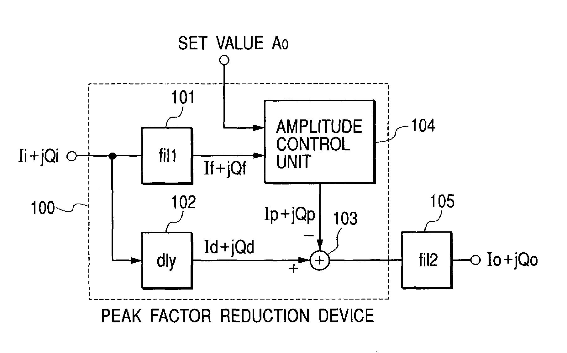
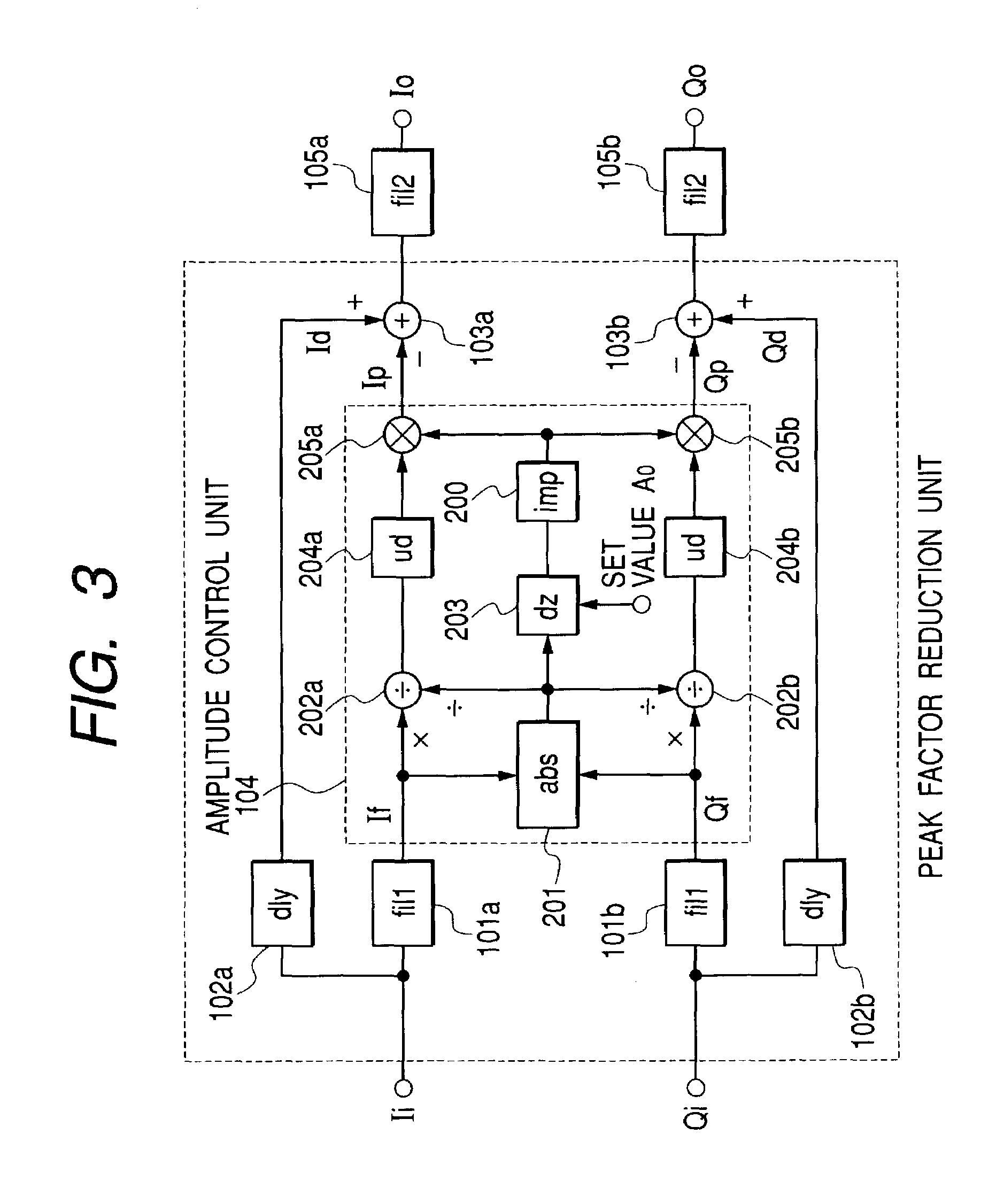
[0034]Hereinafter, with reference to the first embodiment shown in FIG. 3 and an embodiment of the impulse generating circuit shown in FIG. 6, the description will be made of details of the present invention. FIG. 3 shows a base band signal processing unit using a peak factor reduction device according to the present invention.

[0035]In the peak factor reduction device of FIG. 3, first each of a real part Ii and an imaginary part Qi of a normal property base band complex input signal having a uniform spectrum is band-limited by reference filters 101a and 101b. Impulse responses of the reference filters 101a and 101b are assumed to be the same as or exceedingly similar to those of band limiting filters 105a and 105b. Signals band-limited by the reference filters 101a and 101b have still normal property.

[0036]Next, in an absolute value circuit 201, square sums of the real part and the imaginary part are calculated from the complex signal band-limited to take their square root, whereby ...

third embodiment

[0052]Next, with reference to FIG. 9, the description will be made of the third embodiment according to the present invention. The present embodiment is constructed by adding, to a peak factor reduction unit according to the present invention, absolute value circuits 901a and 901b for taking absolute values of output from the reference filters 101a and 101b; an adder 902 for taking a sum of the absolute value circuits 901a and 901b; and a control circuit 903 for controlling so as to suspend the amplitude control unit 104 if the adder 902 output is below A0 on the basis of the same set value A0 as the dead zone circuit 203.

[0053]The amplitude control unit 104 requests an instantaneous amplitude component of the complex signal lf+jQf by the absolute value circuit 201. At this time, since a triangular inequality |lf|+|Qf|≧|lf+jQf| holds concerning the complex signal, A0≧|lf+jQf| will be formed if A0≧|lf|+|Qf|. Therefore, the output from the absolute value circuit 201 is zero, and since...

fourth embodiment

[0054]Next, with reference to FIG. 12, the description will be made of the fourth embodiment according to the present invention. A radio transmitter according to the present invention shown in FIG. 12 is composed of: a spreader 1201 for spreading at least one or more digital modulation signals through the use of a spreading code; a multiplexing unit 1202 for multiplexing a signal spread; an interpolator 1203 for oversampling an output signal from the multiplexing unit; a peak factor reduction device 100 according to the present invention; a band-limiting filter 105 for band-limiting an output signal from the peak factor reduction device; a digital-to-analog converter 1204 for converting a digital output signal to an analog signal; a filter 1205 for smoothing an analog output signal; a frequency modulation unit 1206 for converting the signal band from base band to high-frequency; a power amplifier 1207 for performing signal amplification to a predetermined power; and a control unit 1...


PUM


Abstract

In the conventional peak factor reduction technique, since the signal has been changed over broad time width before and behind the peak amplitude, the deterioration in signal quality has been great. Through the use of a compensating signal having impulse property that is generated on the peak amplitude, subtraction from the peak amplitude will be performed. Thereby, since it is possible to reduce the deterioration in signal quality that occurs when reducing the peak factor, the peak factor reduction effect can be further enhanced in the same deterioration in signal quality as the conventional one.

Description

BACKGROUND OF THE INVENTION[0001]1. Field of the Invention[0002]The present invention relates to a base band signal processing device for a radio transmitter to be used for a mobile communication base station and the like, and more particularly to a base band signal processing device for CDMA base station requiring handling of a signal that conforms to normal distribution having a big peak factor.[0003]2. Description of Related Art[0004]In recent years, CDMA having high utilization efficiency of frequency resources as a mobile communication system, and capable of broad band / high multiplex communication has received attention. In the CDMA system, it is known that since base band signals of more than one channel are spread into non-correlated signals in an artificial way by means of spreading codes that intersect each other at right angles and are transmitted with their codes multiplexed, when a number of multiplexing is increased, a transmission I, Q signal approaches the normal dist...

Claims


Application Information

Patent Timeline
Patent Type & Authority Patents(United States)
IPC IPC(8): H04B1/04H04L27/36H04B1/707H04J13/00H04L27/26
CPCH04B1/707H04B2201/70706
Inventor HORI, KAZUYUKIYANO, TAKASHI
Owner HITACHI LTD
Why Eureka
Try Eureka