Direct drive assembly and go-kart containing same

a technology of direct drive and drive shaft, which is applied in the direction of propulsion parts, transportation and packaging, understructures, etc., can solve the problems of limiting the extent to which the driven sprocket on the rear-wheel drive shaft can be made larger, hitting the ground, and unable to rotate the pinion, so as to reduce the user's maintenance costs

Inactive Publication Date: 2006-02-21
BOMBARDIER ROTAK GMBH
View PDF38 Cites 17 Cited by
  • Summary
  • Abstract
  • Description
  • Claims
  • Application Information

AI Technical Summary

Benefits of technology

[0007]It is the objective of the present invention to describe a go-kart drive assembly of the type described in the introduction hereto, which is based on a compact engine-transmission assembly, which eliminates the difficulties outlined above, and which minimizes the user's maintenance costs.
[0008]In order to achieve this objective, in a go-kart drive assembly of the type defined heretofore the present invention stipulates that the spur-type gearing, with the crankshaft of the reciprocating-piston engine or the engine shaft of the rotary-piston engine, be accommodated in a common, preferably enclosed, housing such that the space(s) between the gear-wheel shafts be invariable; and such that the driving gear wheel of the gearing be mounted on the crankshaft or engine shaft, and the driven gear wheel be installed on the rear-wheel drive shaft. In the case of spur-type multi-stage gearing, provision is made for specified, unchangeable spacing of the shafts between the individual stages of the gearing; the driving gear wheel of the first stage of the gearing is mounted on the crank shaft or engine shaft, and the driven gear wheel of the final stage of the gearing is mounted on the rear-wheel drive shaft. In total, this results in a compact drive assembly with precisely aligned gear wheels in the form of a direct drive for the rear-wheel drive shaft of the go-kart. In order to prevent oil leaks, it is preferred that the common housing be enclosed.
[0009]More advantageously, the driving pinion of the gearing (in the case of multi-stage gearing, the first stage of the gearing) is mounted on the crank shaft or engine shaft in such a way that it can rotate, and is connected to the crank shaft or engine shaft through a clutch, preferably a centrifugal clutch, so that engine torque can be applied to the gearing in an efficient manner.
[0011]In the first instance, the rear-wheel drive shaft can be installed directly in the engine-transmission housing in such a manner that it can rotate. It is preferred that the driven gear wheel of the gearing (or of the final stage of the gearing) be connected to the rear-wheel drive shaft through a connecting element, e.g., a bolt, so as to be removable, said connecting element being accessible through a closable opening in the housing. The rear-wheel drive shaft can be made in three sections and consist of a centre section of the shaft that is arranged in the housing so as to be able to rotate therein, and two other shaft sections; one end of each of these outer shaft sections is connected to the centre section of the shaft so as to be removable therefrom, i.e., by means of a bolted connection. At their outboard ends, each of these two sections of the shaft supports a rear wheel. Dividing the rear-wheel drive shaft in this way entails the advantage that should the shaft fail, only the affected section of the shaft need be replaced, which results in a significant reduction in the time and cost of repairs.
[0012]In the second instance, the rear-wheel drive shaft can be installed indirectly in the housing—through the driven pinion of the gearing, (or the last stage of the gearing) that is made in one piece with a hollow shaft—so as to be able to rotate within the housing. In this case, the rear-wheel drive shaft is connected to the hollow shaft in such a way that it is removable, e.g., by being keyed onto the shaft. A flexible coupling, e.g., a rubber element and / or a friction clutch, can be used to damp torsional oscillations and to provide protection against load peaks. Generally speaking, in order to avoid torque peaks in the drive train, it is advantageous if an overload coupling be incorporated in the drive train.
[0016]The two-stage gearing described above which is the preferred type, also permits the space-saving integration of a balance weight, a starter assembly, and a water pump,

Problems solved by technology

For technical reasons, smaller pinions cannot be made.
On the other hand, there is a limit to the extent to which the driven sprocket on the rear-wheel drive shaft can be made larger because of the low ground clearance of the vehicle.
If the driven sprocket is too large, it will hit the ground.
Such extreme operating conditions, combined with the high speed at which the chain moves—modern go-kart engines run at speeds of up to 21,000 rpm—place extremely high stresses on the chain drive system and these are linked to high rates of wear, a rapid loss of efficiency, short service life, and excessive noise.
The outcome is that the chain, which is costly in and of itself, as well as the sprocket, have to be replaced at very short intervals.
One disadvantage with this concept is that it is extremely difficult to achieve the precise alignment of two spur gears that mesh with each other, which is necessitated by such gearing, if the variable engine installation concept that has been proposed is used.
Small misalignments inevitably lead to greater stresses, increased wear, and to even more noise.
An additional disadvantage is the fact that complete encapsulation of the transmission is difficult because of the separation of the engine from the transmission, and because of the variable engine mounting; in addition, an installation of this kind makes it almost impossible to avoid oil leaks.

Method used


Image

  • Direct drive assembly and go-kart containing same
  • Direct drive assembly and go-kart containing same
  • Direct drive assembly and go-kart containing same

Examples


Embodiment Construction

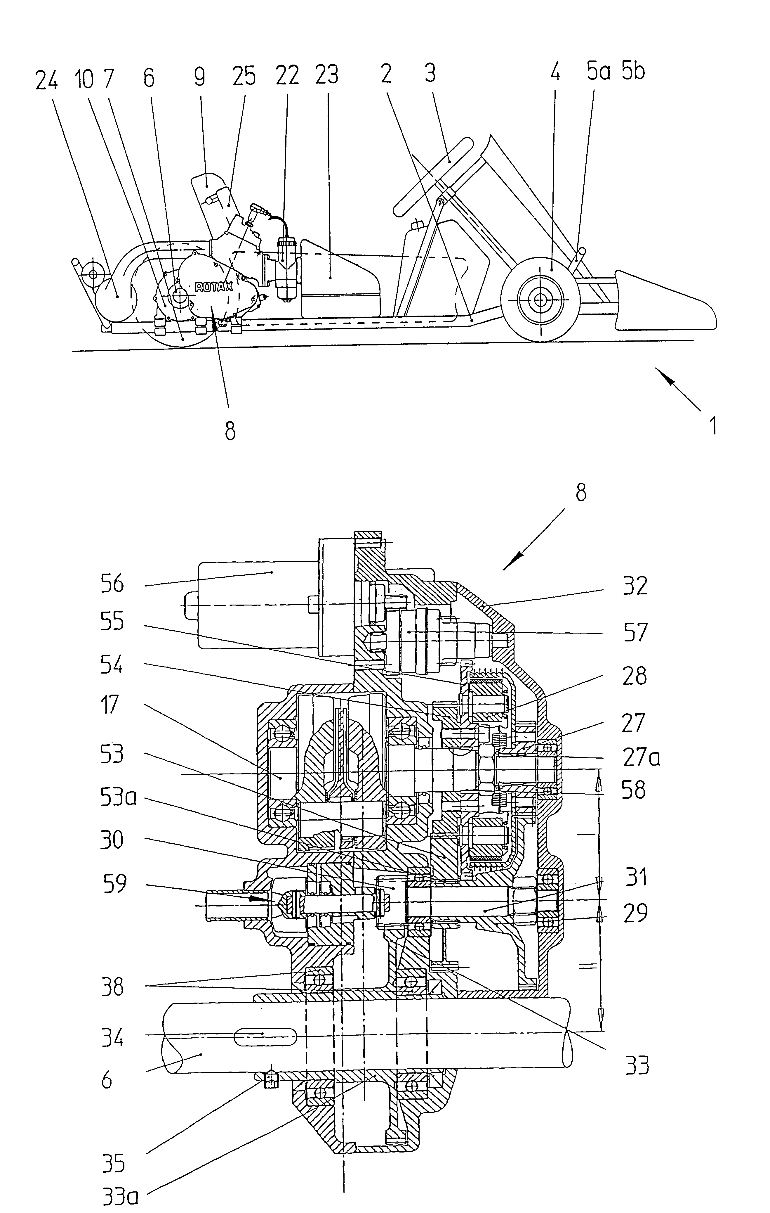
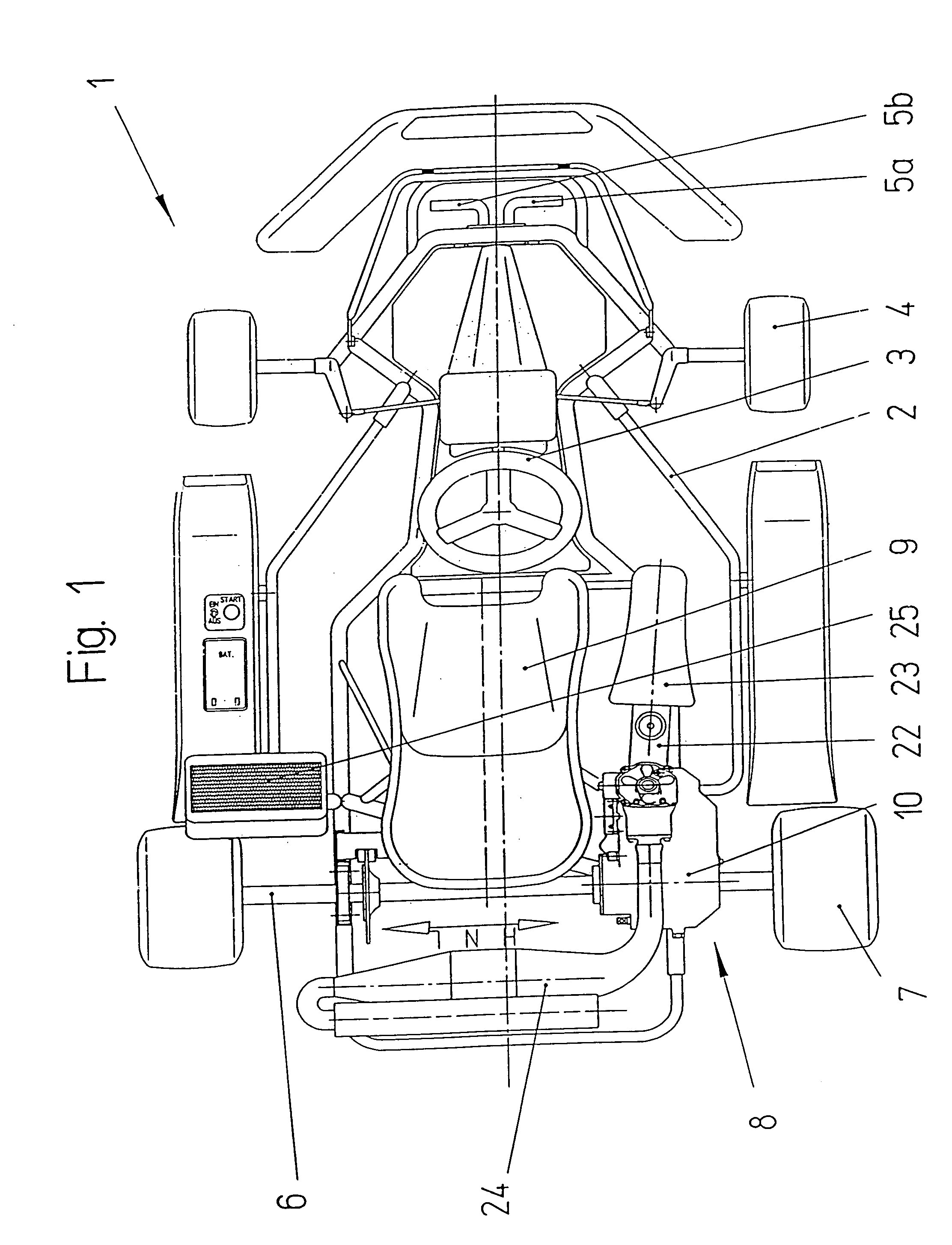
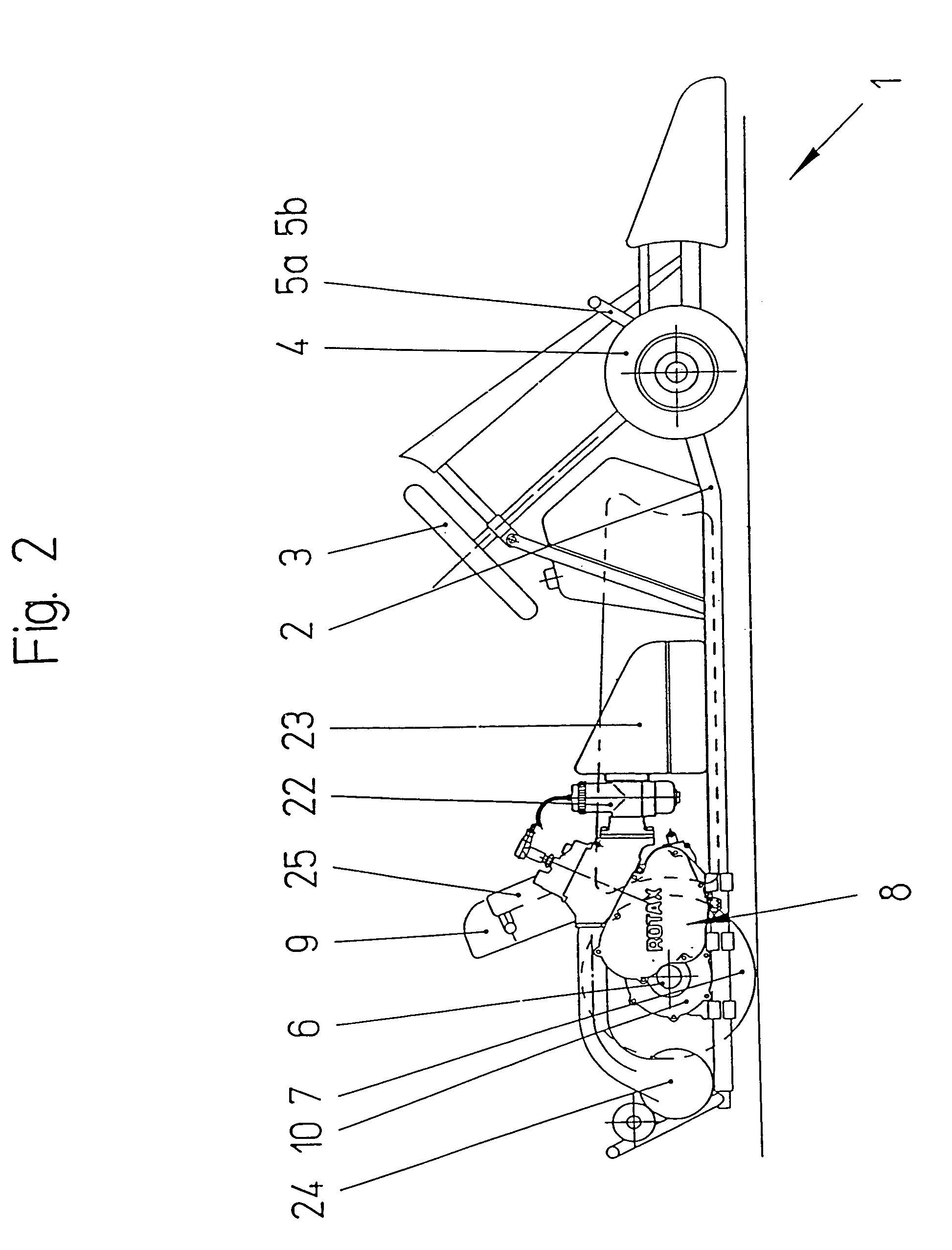
[0035]FIG. 1 and FIG. 2 show a motor vehicle 1, generally referred to as a go-kart, which is used for leisure and sporting activities. This vehicle has a chassis 2 that is a tubular structure, hereinafter referred to as a tubular chassis, on the front of which there are front wheels 4 that can be steered by a steering wheel 3. In addition, in the front part of the vehicle, there are pedals 5a and 5b, usually an accelerator pedal and a brake pedal: In the rear part of the tubular chassis 2 there is a rear-wheel drive shaft 6 that has wheels 7 mounted on its ends and which is driven by an engine-transmission unit 8. The engine-transmission unit 8 is arranged ahead of the rear-wheel drive shaft 6, to one side of the driver's seat, and is secured to the tubular chassis 2. At the engine end, the rear-wheel drive shaft 6 is supported in an engine-transmission housing 10 and at the opposite end in the tubular chassis 2. In principle, it would be possible to use a twin-engine drive system (...


PUM


Abstract

A go-kart drive assembly with an internal combustion engine in the form of a reciprocating-piston or rotary-piston engine as a power source is described. The drive assembly includes a spur-gear reduction gearing between the internal combustion engine and a rear-wheel drive shaft of the go-kart. The spur-gear reduction gearing and the crank shaft (17) of the reciprocating engine or the engine shaft of the rotary-piston engine (17a) are accommodated in a common housing (10) that is preferably closed. The space or spaces (a, b) between the shafts of the spur-gear reduction gearing (27, 29; 30, 33) is fixed in the housing (10) so as to be invariable. The driving gear wheel (27) of the gearing (26) is mounted on the crank shaft (17) or the engine shaft (17a) and the driven gear wheel (33) of the gearing (26) is mounted on the rear-wheel drive shaft (6).

Description

FIELD OF THE INVENTION[0001]The present invention relates to a go-kart drive assembly comprising an internal-combustion engine in the form of a reciprocating-piston or rotary-piston engine as the power source, and with spur-gear reduction gearing between the internal-combustion engine and a go-kart rear-wheel drive shaft; the present invention also relates to a go-kart with such a drive assembly.BACKGROUND OF THE INVENTION[0002]Go-karts are motor vehicles that are used for leisure and sporting activities. In go-karts, a chain is usually used to transmit power from the engine to the rear-wheel drive shaft; this chain is routed around a engine pinion and a sprocket that is mounted on the rear-wheel drive shaft. In order to achieve the large reduction ratio that is needed by using this single-stage chain drive, it is necessary to make the engine pinion extremely small (tooth count: 9–11). For technical reasons, smaller pinions cannot be made. On the other hand, there is a limit to the ...

Claims


Application Information

Patent Timeline
Patent Type & Authority Patents(United States)
IPC IPC(8): B60K5/04B60K17/04
CPCB60K17/04B60G2300/26B60Y2200/114
Inventor KORENJAK, NORBERTRUTERSHOFF, BERNHARD
Owner BOMBARDIER ROTAK GMBH
Why Eureka
Try Eureka