Delay time modulation femtosecond time-resolved scanning probe microscope apparatus

a scanning probe microscope and time-resolved technology, applied in the direction of fluorescence/phosphorescence, optical radiation measurement, instruments, etc., can solve the problems of generators with long-period fluctuation, insufficient measurement precision, and conventional apparatuses mentioned above, and achieve high sensitivity and high precision.

Inactive Publication Date: 2006-02-21
JAPAN SCI & TECH CORP
View PDF10 Cites 11 Cited by
  • Summary
  • Abstract
  • Description
  • Claims
  • Application Information

AI Technical Summary

Benefits of technology

[0024]Further, making the delay time modulation frequency much higher than the frequency of fluctuations in intensity of ultrashort laser pulses allows a delay time dependent, minute component of the probe signal to be detected unaffected by such fluctuations in intensity of ultrashort laser pulses.
[0025]Furthermore, irradiating the specimen just below the probe with all the ultrashort laser pulses produced in a train by the ultrashort laser pulse generator at a fixed periodicity—rather than with those in part interrupted such as by a chopper as in the prior art—while making the frequency of ultrashort laser pulses produced much higher than the thermal response frequency at the probe apex permits the probe apex to be supplied with ultrashort light pulses continuously and with no time in which it is allowed to cool and thus to hold its temperature substantially constant. This will prevent the probe apex from repeatedly thermally expanding and contracting, prevent its distance from the surface of the specimen from changing and eventually prevent the tunneling probability from fluctuating. As a result, it is made possible to measure a delay time dependent, minute component of the probe signal at both high sensitivity and high precision. Also, the use of the scanning probe providing a spatial resolution in the order of angstroms allows a delay time dependent, minute component of the probe signal to be detected at a spatial resolution in the order of angstroms, hence at both high sensitivity and high precision.
[0026]Thus, according to the present invention that allows a probe signal component dependent on a delay time between exciting light pulses at a spatial resolution in the order of angstroms and at a temporal resolution in the order of femtoseconds to be directly measured at high sensitivity and precision, it becomes possible to measure a photoexcited physical phenomenon at an ultimate resolution both spatial and temporal.
[0030]With the apparatus constructed as mentioned above, a probe signal component that is dependent on a delay time between exciting light pulses at a spatial resolution in the order of angstroms and at a temporal resolution in the order of femtoseconds can be directly measured at both high sensitivity and high precision as with the delay time modulated and femtosecond time-resolved scanning microscope apparatus as set forth in claim 1. Moreover, it permits a probe signal component that is dependent on a delay time between exciting light pulses different in wavelength and of wavelengths as desired to be directly measured at high sensitivity and precision. Accordingly, it makes it possible for a photoexcited physical phenomenon in which three or more energy levels take parts to be measured at an ultimate resolution both spatial and temporal.

Problems solved by technology

The conventional apparatus mentioned above has presented problems as described below, however.
First, the probe signal component that is dependent on the delay time td is much smaller than the component that is not dependent on the delay time td, and cannot be measured with enough precision even if the dynamic range of the lock-in device is increased to its limit.
Second, the light output intensity of the ultrashort laser light pulse generator has a long-period fluctuation due to a small change in environment (such as temperature etc.) which fluctuation, however, cannot be eliminated by the conventional technique; hence it is hard to determine the delay time dependency of the probe signal at sufficient precision.
Thus, as far as the conventional technique is concerned in which a difference in probe signal between when light is irradiated and when it is not irradiated is relied on, it has been found to be difficult to measure the delay time dependency of the probe signal component at sufficient sensitivity and precision.
Third, the probe apex in the scanning probe microscope, when irradiated with ultrafast laser pulses, is thermally elongated, while it shrinks when the laser pulses are turned off.
This results in changes in the spacing between the probe apex and specimen surface and in turn in changes in the tunneling probability between them.
Thus, here again there ensues the difficulty in measuring the delay time dependency of the probe signal at both high sensitivity and high precision.
Thus, while such an apparatus permits measuring a phenomenon in which two energy levels participate, it cannot measure a photoexcited phenomenon in which three or more energy levels take parts.
However, the prior-art apparatus cannot have two short light pulses that have different wavelength to each other.

Method used


Image

  • Delay time modulation femtosecond time-resolved scanning probe microscope apparatus
  • Delay time modulation femtosecond time-resolved scanning probe microscope apparatus
  • Delay time modulation femtosecond time-resolved scanning probe microscope apparatus

Examples


Embodiment Construction

[0042]Hereinafter, the present invention will be described in detail with reference to certain suitable forms of implementation thereof illustrated in the drawing figures.

[0043]Mention is first made of a delay time modulated and femtosecond time-resolved scanning probe microscope apparatus constituting a first form of implementation of the present invention.

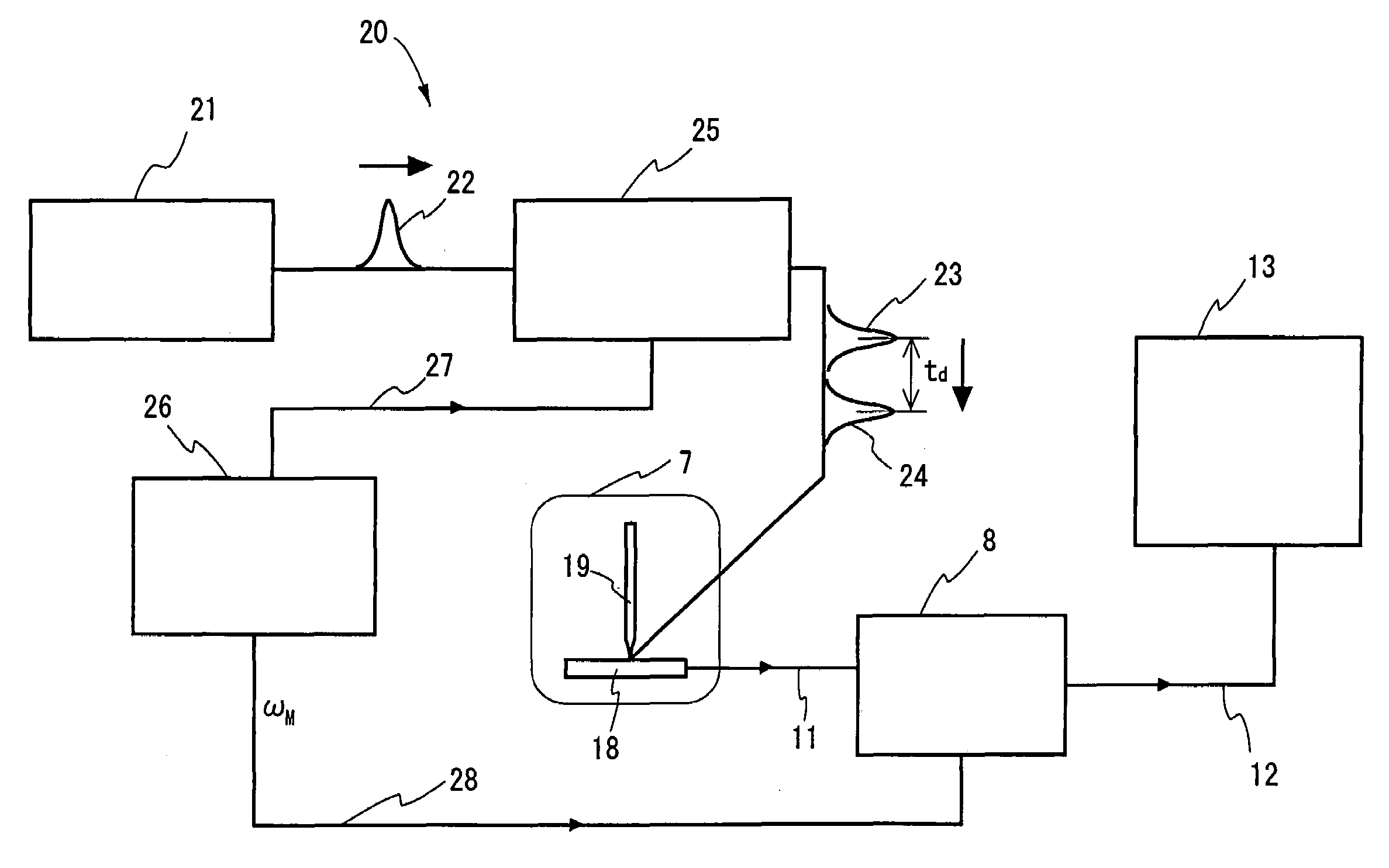
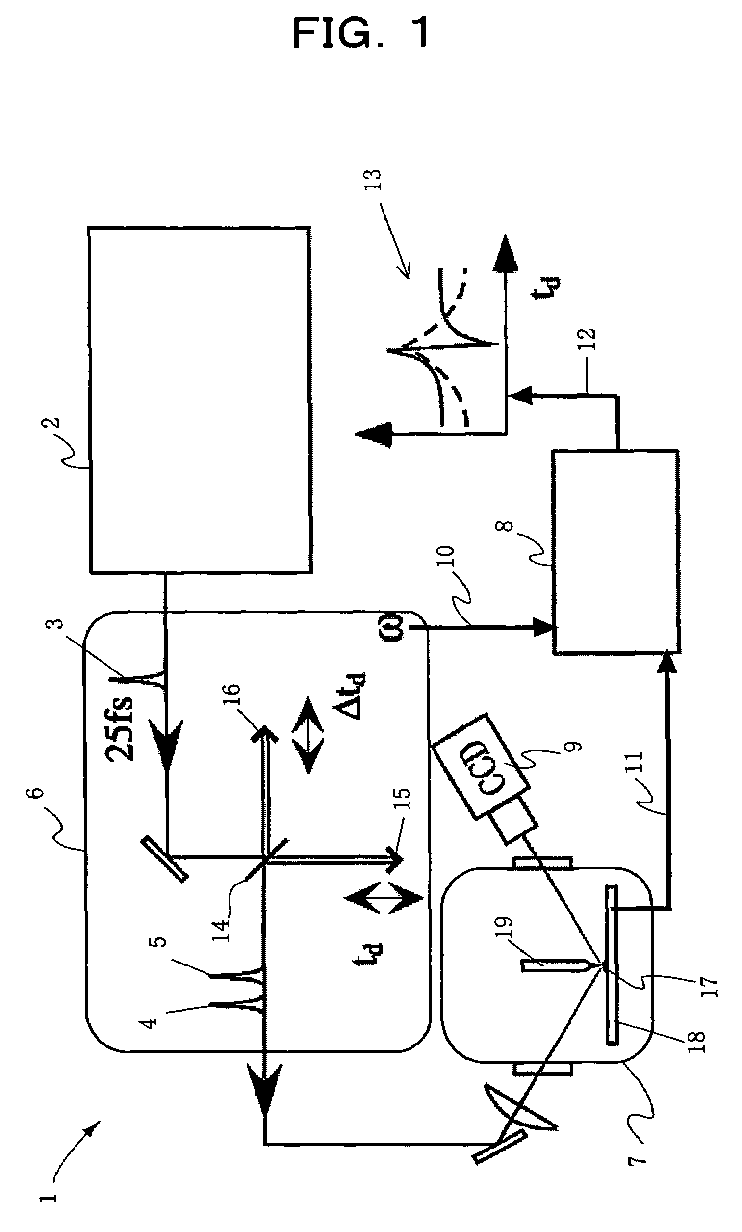
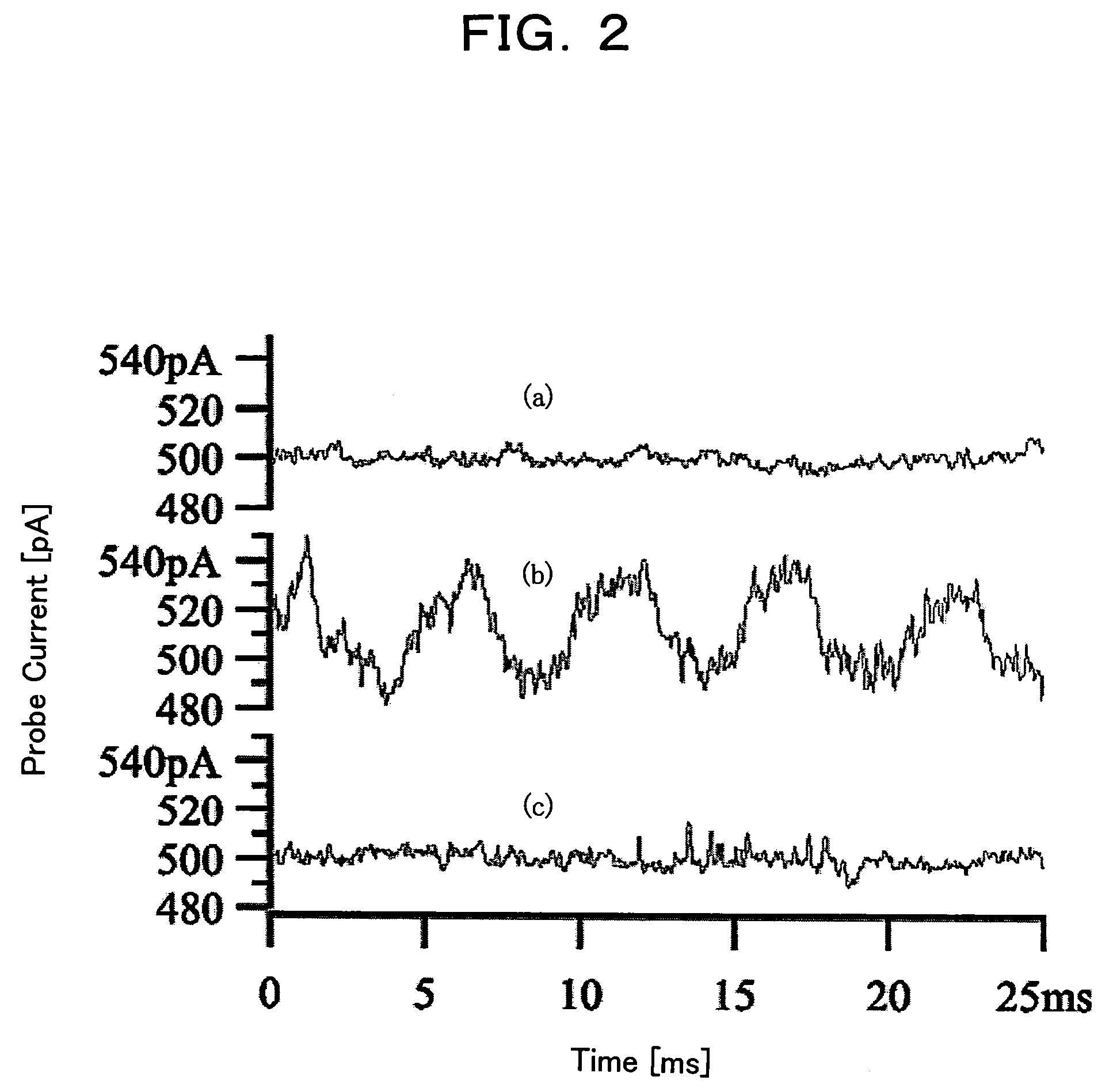
[0044]FIG. 1 is a diagram illustrating the construction of a delay time modulated and femtosecond time-resolved scanning probe microscope apparatus constituting a first form of implementation of the present invention. In the Figure, the delay time modulated and femtosecond time-resolved scanning probe microscope apparatus of the present invention designated by reference numeral 1 comprises an ultrashort laser pulse generator 2 for producing a series of ultrashort laser pulses 3; a delay time modulating circuit 6 which splits an ultrashort laser pulse 3 produced by the ultrashort laser pulse generator 2 into two ultrashort laser p...


PUM

PropertyMeasurementUnit
delay timeaaaaaaaaaa
repetition frequencyaaaaaaaaaa
wavelengthaaaaaaaaaa

Abstract

Disclosed is a measuring apparatus for a physical phenomenon by photoexcitation, in particular a delay time modulated and time-resolved, scanning probe microscope apparatus providing an ultimate resolution both temporal and spatial. The apparatus comprises an ultrashort laser pulse generator (2); a delay time modulating circuit (6) which splits an ultrashort laser pulse (3) produced by the ultrashort laser pulse generator (2) into two and which also modulates a delay time td between the two ultrashort laser pulses (4 and 5) with a frequency (ω); a scanning probe microscope (7); and a lock-in detection unit (8) which performs lock-in detection with the delay time modulation frequency (ω) of a probe signal (11) from the scanning probe microscope (7). It can detect the delay time dependency of the probe signal (11) as its differential coefficient to the delay time, with no substantial influence from fluctuations in the intensity of ultrashort laser pulses (3) while preventing the probe apex (19) from thermal expansion and shrinkage by repeated irradiation with ultrashort laser pulses (3). A photoexcited physical phenomenon dependent on a delay time between ultrashort laser pulses can thus be measured at a temporal resolution in the order of femtoseconds and at a spatial resolution in the order of angstroms.

Description

TECHNICAL FIELD[0001]The present invention relates to an apparatus for measuring a physical phenomenon by photoexcitation, which has an ultimate resolution both temporal and spatial. More specifically, the invention relates to a delay time modulated and time-resolved, scanning probe microscope apparatus.BACKGROUND ART[0002]Attempts to develop next-generation devices having unprecedented functions by controlling structures on nanoscale have been growing rapidly in late years. Among others, creating a functional device and an ultrafast device utilizing photophysical properties is one of particularly important targets. To this end, it becomes necessary and essential to elucidate a photoexcited physical phenomenon in a local area of nanoscale, including a transient response therein. In this connection, it has been proposed to introduce a new measurement technique that combines a scanning probe microscopic technique providing an ultimate spatial resolution with a laser pulse technique pr...

Claims


Application Information

Patent Timeline
Patent Type & Authority Patents(United States)
IPC IPC(8): H01J37/00G01J1/42G01J3/28G01J3/433G01N21/64G01Q30/00G01Q30/02G01Q60/10G01Q60/24
CPCB82Y35/00G01J3/2889G01J3/433G01Q30/02G01N21/6408G01J2001/4242Y10S977/85G01N21/6458G01N2021/6415G01Q60/12
Inventor SHIGEKAWA, HIDEMITAKEUCHI, OSAMUYAMASHITA, MIKIOMORITA, RYUJI
Owner JAPAN SCI & TECH CORP
Why Eureka
Try Eureka