Electrical fuse for integrated circuits

Active Publication Date: 2006-02-21
XILINX INC
View PDF5 Cites 15 Cited by
  • Summary
  • Abstract
  • Description
  • Claims
  • Application Information

AI Technical Summary

Benefits of technology

[0009]According to an embodiment of the invention, an electrically programmable fuse is formed by coupling a regulating element between the source and gate of a programmable transistor for lowering snapback voltage of the transistor below its nominal snapback voltage. According to an embodiment of the invention, the programmable transistor comprises a first n-type metal-oxide-semiconductor (NMOS) transistor, in which case the regulating element can com

Problems solved by technology

However, since an external programming tool (e.g., a laser) can sometimes be cumbersome, it is often desirable for fuses to be electrically programmable.
When a programming voltage is applied across the gate heating element, the gate heating element raises the temperature of the device in the channel region, which results in dopant migration.
However, the high temperature provided by

Method used


Image

  • Electrical fuse for integrated circuits
  • Electrical fuse for integrated circuits
  • Electrical fuse for integrated circuits

Examples


Embodiment Construction

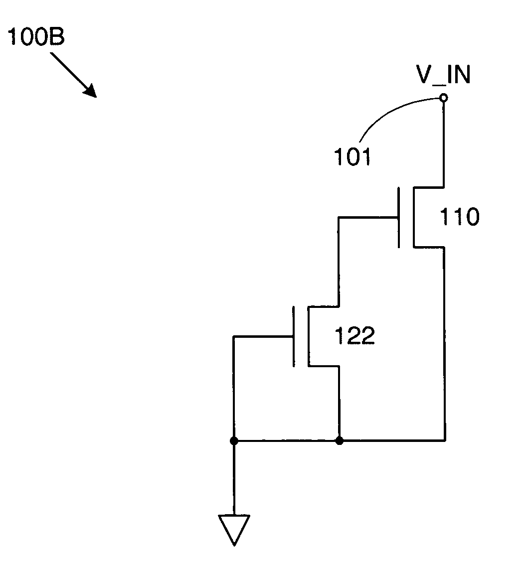
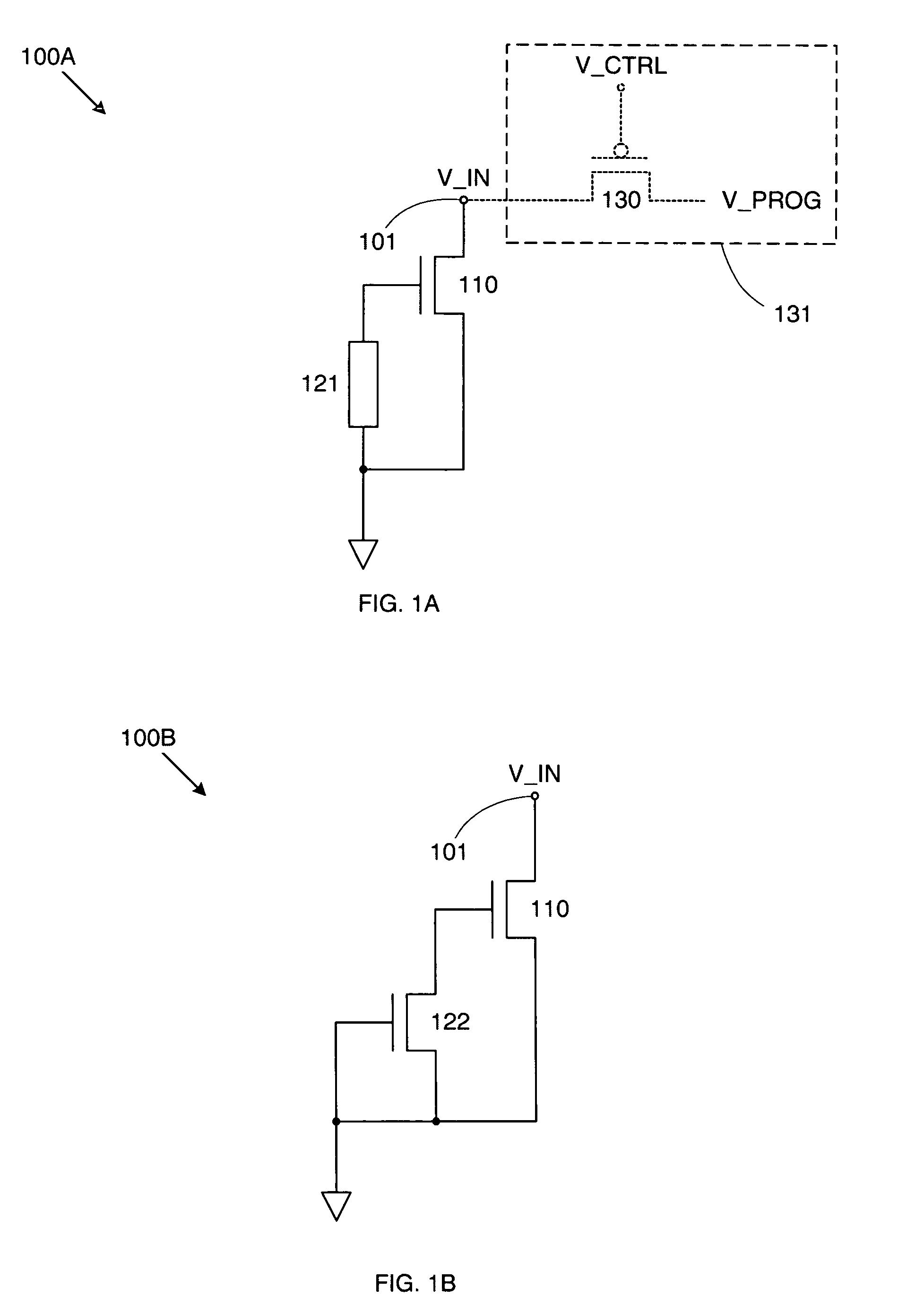
[0018]FIG. 1A shows an electrically programmable fuse 100A in accordance with an embodiment of the invention. Fuse 100A includes an NMOS programmable transistor 110 and a resistive element 121. Resistive element 121 can comprise any structure or device that provides a desired resistance (e.g., a polysilicon resistor). The drain of programmable transistor 110 is connected to an input terminal 101, while the source of programmable transistor 110 is connected to ground. (Note that as used herein, “ground” refers to the lower supply voltage of the circuit that includes the fuse of the invention.)

[0019]Meanwhile, resistive element 121 is connected between the gate and source of programmable transistor 110, thereby coupling the gate of programmable transistor 110 to ground. As a result, when fuse 100A is in an unprogrammed state, programmable transistor 110 is essentially off—i.e., when an input voltage V_IN at input terminal 101 is equal to a read voltage (typically the nominal operating...


PUM


Abstract

An electrically programmable fuse includes a metal-oxide-semiconductor (MOS) programmable transistor that is gate-source coupled by a resistive element. The resistive element can comprise a gate-source coupled MOS transistor. If the MOS transistor is unprogrammed, then the resistive element ensures that the programmable transistor is turned off during read operations. However, when a programming voltage is applied across the source and drain terminals of the programmable transistor, the resistive element allows the programming voltage to be capacitively coupled to the gate of the programmable transistor from its drain. This turns the programmable transistor on, thereby reducing the snapback voltage of the programmable transistor, and hence, the required programming voltage. Once the snapback mode is entered, current flow through the programmable transistor increases until thermal breakdown occurs and the programmable transistor shorts out. The programmable transistor will then behave as a constant-on transistor during all subsequent read operations.

Description

BACKGROUND OF THE INVENTION[0001]1. Field of the Invention[0002]The invention relates to programmable integrated circuits, and in particular, to an electrically programmable fuse.[0003]2. Related Art[0004]It is often beneficial for an integrated circuit (IC) to include one or more one-time programmable elements (fuses). For example, static random access memories (SRAMs) often include metal fuses that can be blown open with a laser to activate redundancy circuitry, thereby improving production yields. As another example, programmable logic devices (PLDs), such as a field programmable gate array (FPGA), may also include fuses for activating redundant resources, storing encryption or security keys, or other purposes. A PLD may include configurable resources, such as configurable logic, a configurable interconnect structure, programmable input / output blocks, memories, transceivers, and processors. Fuses in a PLD may be used to control some or all of the configurable resources.[0005]Howe...

Claims


Application Information

Patent Timeline
IPC IPC(8): H01L23/62H01L31/0392
CPCH01L23/5256H01L2924/0002H01L2924/00
Inventor DE JONG, JAN L.KARP, JAMESNGUYEN, LEON LY
Owner XILINX INC
Why Eureka
Try Eureka