
Ventilated double-walled composite aircraft fuselage shell

a composite aircraft and fuselage shell technology, applied in envelope/bag making machinery, paper/cardboard containers, other domestic articles, etc., can solve the problems of unsuitable conventional composite structural components for use in the primary fuselage shell, the accumulation of condensate moisture, and the undesirable moisture uptake of known double-walled composite structures in servi

Inactive Publication Date: 2006-02-28
AIRBUS OPERATIONS GMBH
View PDF19 Cites 44 Cited by
  • Summary
  • Abstract
  • Description
  • Claims
  • Application Information

AI Technical Summary

Benefits of technology

The invention provides a double-walled composite core structure for use in the primary structure of an aircraft fuselage shell. The core element is ventilated and not sealed in an airtight manner, allowing air to flow through it in at least one direction. This structure prevents the accumulation of moisture and improves acoustic and thermal insulation properties, as well as increases fire protection against total fire penetration or fire destruction of the component.

Problems solved by technology

The build-up of condensate moisture has long been a problem in an aircraft fuselage wall or shell forming the primary load-bearing wall structure of the aircraft airframe.
However, such structural components have always only been used as secondary components, and have not been used in the primary structure of the airframe, e.g. the aircraft fuselage shell, of an aircraft, for various reasons.
Most importantly, the known double-walled composite structures suffer an undesirable moisture uptake in service, whereby the structures accumulate condensed moisture in the substantially sealed core, after moist cabin air permeates into the core through a cover layer of the structure, or through small gaps or mounting holes or the like.
Therefore, such conventional composite structural components are not suitable for use in the primary fuselage shell, due to the accentuated condensation problems as discussed in the preceding paragraph.
Also, the known double-walled composite structures are rather susceptible to damage and consequently require repair.

Method used


Image

  • Ventilated double-walled composite aircraft fuselage shell
  • Ventilated double-walled composite aircraft fuselage shell

Examples


Embodiment Construction

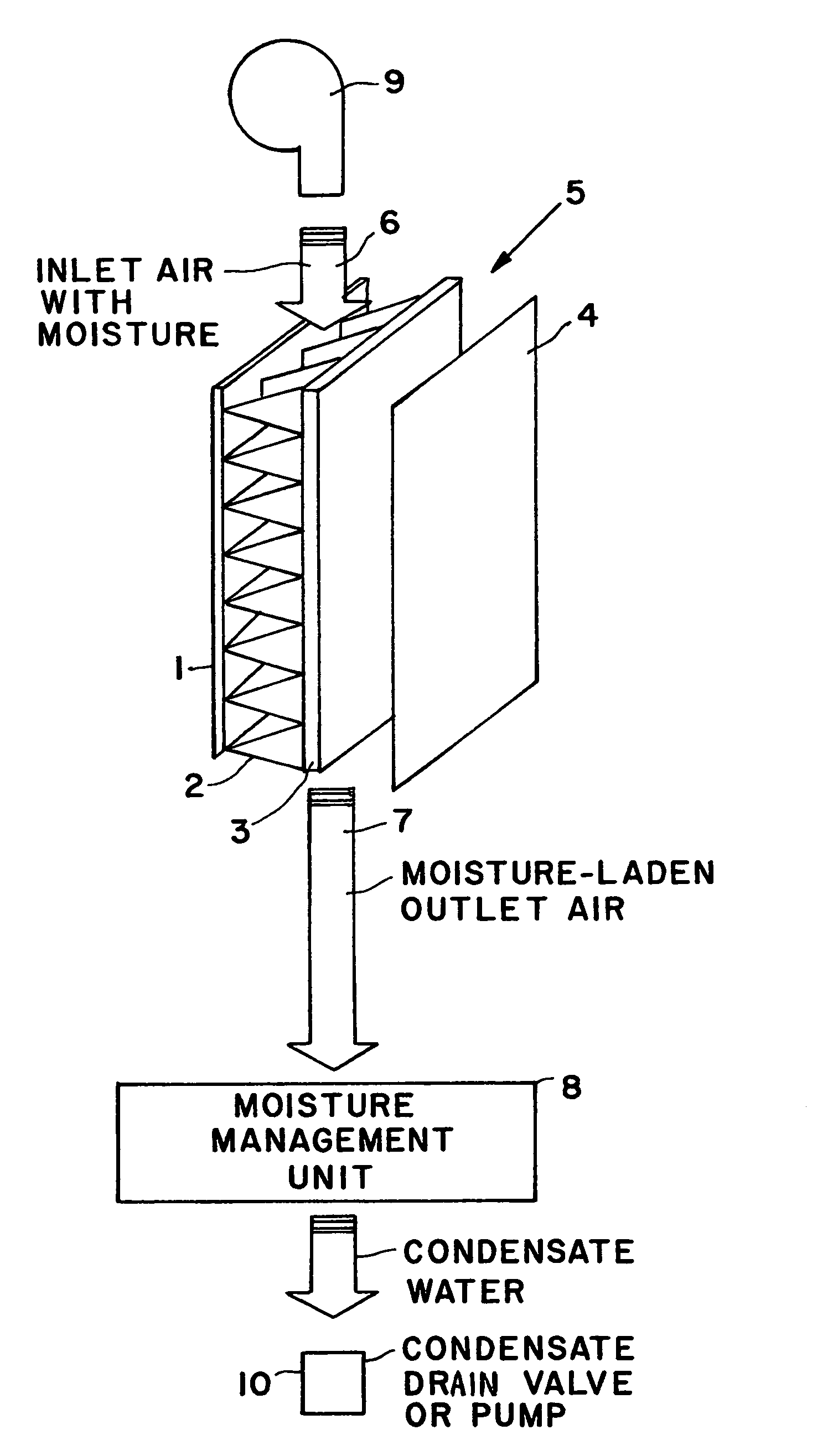
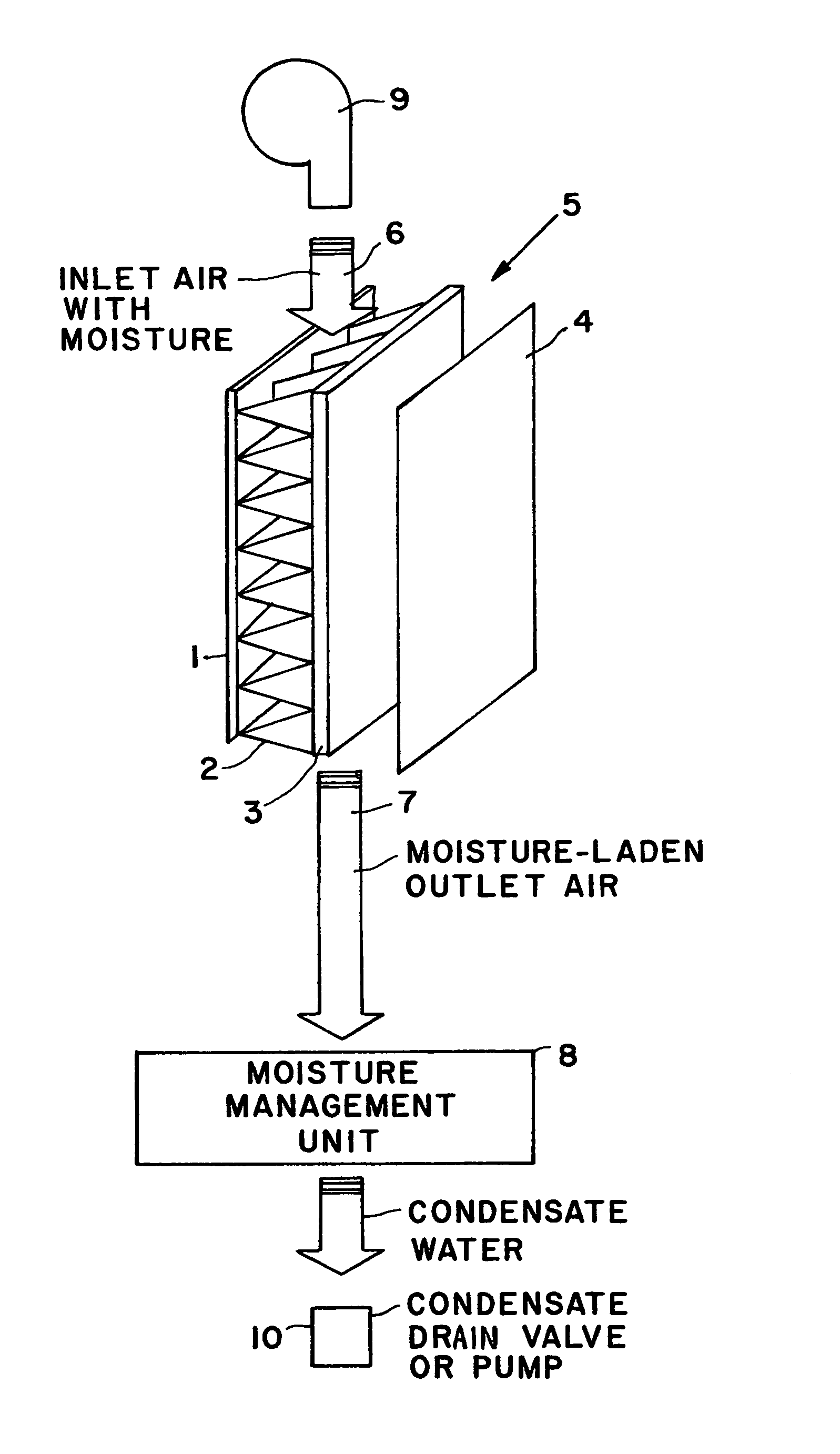
[0010]As shown schematically in the single drawing FIGURE, the double-walled composite core structural component 5 according to the invention comprises two cover layers 1 and 3 consisting of fiber-reinforced composite synthetic material, for example. The cover layers 1 and 3 may alternatively consist of an aluminum alloy, or some other metal. One cover layer 1 forms the outer skin and the other cover layer 3 forms the inner skin of an aircraft fuselage shell. The inner cover layer 3 forming the inner skin of the aircraft fuselage shell carries the major loads, i.e. the majority of the total load to be carried by the fuselage shell during service. On the other hand, the outer cover layer 1 carries a relatively smaller proportion of the loads, e.g. of the active loads arising during operation. For schematic simplicity, the composite core structural component 5 is shown as substantially flat or planar, but in actual practice the composite structural component 5 may have a curved config...


PUM

PropertyMeasurementUnit
air permeableaaaaaaaaaa
folded cell structureaaaaaaaaaa
concave curvatureaaaaaaaaaa

Abstract

An aircraft fuselage shell is fabricated of a double-walled composite structural component, including a core element bonded and sandwiched between an inner cover layer and an outer cover layer. The inner cover layer forms the main load bearing fuselage inner skin, and the outer cover layer forms the fuselage outer skin which carries a smaller proportion of the loads. The core element may consist of fiber-reinforced composite material while the cover layers may consist of an aluminum alloy, another metal, or fiber-reinforced composite material. The core element is air permeable and has air flow channels extending longitudinally therethrough in at least one direction. The cover layers do not seal or enclose the core element, so the core element is ventilatable. A ventilating airflow carries moisture as water vapor out of the core element, and then the moisture is condensed and removed by a moisture management unit.

Description

PRIORITY CLAIM[0001]This application is based on and claims the priority under 35 U.S.C. §119 of German Patent Application 101 54 063.9, filed on Nov. 2, 2001, the entire disclosure of which is incorporated herein by reference.FIELD OF THE INVENTION[0002]The invention relates to a double-walled composite core structural component, preferably comprising a fiber composite material, and including a core element that is sandwiched between two cover layers of aluminum, some other metal, a fiber-reinforced composite material, or the like.BACKGROUND INFORMATION[0003]The build-up of condensate moisture has long been a problem in an aircraft fuselage wall or shell forming the primary load-bearing wall structure of the aircraft airframe. Due to the moisture released into the air by the passengers' breath and the like and the natural atmospheric humidity in the cabin air in the enclosed aircraft cabin, and due to the cold temperatures prevailing outside of the aircraft during high altitude fli...

Claims


Application Information

Patent Timeline
Patent Type & Authority Patents(United States)
IPC IPC(8): B32B1/04B32B3/02B64C1/00B32B1/00B32B3/12B32B5/00B32B15/08B32B17/04B64C1/12
CPCB64C1/067Y10T428/239Y10T428/13Y10T428/24942Y10T428/23Y10T428/238
Inventor HACHENBERG, DIETERRUECKERT, CHRISTIAN
Owner AIRBUS OPERATIONS GMBH
Learn More