Polymer surface modification

a polymer surface and polymer technology, applied in the direction of positive displacement liquid engine, flexible pipe, fluid speed measurement, etc., can solve the problems of significant changes in reagent concentration, carryover contamination, and incompatibility of many polymer materials with a variety of reagents

Inactive Publication Date: 2006-02-28
FLUIDIGM CORP
View PDF8 Cites 69 Cited by
  • Summary
  • Abstract
  • Description
  • Claims
  • Application Information

AI Technical Summary

Benefits of technology

[0019]In one embodiment, the surface modifying compound is a biocompatible compound, thereby rendering the surface modified polymer biocompatible. Preferably, the biocompatible polymer is selected from the group consisting of vinyl terminated small molecules, acrylate terminated small molecules, polyethylene glycol, poly(methyl methacrylate), poly(ethylene vinyl acetate), poly(2-hydroxyethyl methacrylate), polyvinylpyrrolidone, CH2═CH-PEG (i.e., allyl-PEG), and CH2═CH—(CH2)n-Teflon®.

Problems solved by technology

Unfortunately, many polymer materials are incompatible with a variety of reagents in many applications.
For example, proteins and other biomolecules tend to adhere to hydrophobic surfaces, and therefore hydrophobic polymers may not be suitable in some applications where proteins and other biomolecules are involved.
Because of a much higher surface area to volume ratio in microfluidic environment, the adsorption of reagents on the surface of the microfluidic devices result in significant changes in reagent concentration and carryover contamination, etc.
In addition, microfluidic devices have extremely small features, e.g., flow channels having width of as small as 1 μm.
Therefore, coating a surface modifying compound may destroy the microfluidic design or render the microfluidic device unusable.
Unfortunately, many linkers and solvents used in these processes are not compatible with a large amount of polymeric materials.
Also, surface activation processes increase the cost and time for producing such polymeric devices.
Moreover, many polymer surface activation processes result in activation of only a small portion of the polymer surface.

Method used


Image

  • Polymer surface modification
  • Polymer surface modification
  • Polymer surface modification

Examples


example 1

[0191]A 3:1 (A:B) GE RTV 615 silicone mixture was cured at 80° C. in a convection oven for 3 hrs. The silicone sample was then immersed in a molten PEG sample (molecular weight 1,000, Polysciences, Inc.) at 80° C. for 24 hrs. The surface treated samples were then repeatedly washed with high purity deionized (i.e., DI) water for 2 hrs. The resulting samples were incubated with conjugated protein solutions for 2 hrs at room temperature. The protein solutions used were: insulin-FITC (1 mg / mL), BSA-FITC (1 mg / mL), IgG-FITC (1 mg / mL) and Strepdavidin-Cy3 (0.2 mg / mL). The PEG grafted silicone samples were then washed with DI water gently three times. Fluorescence microscope was used to record the fluorescence intensity of the samples. The settings of the microscope were at such that the intensity is linearly proportional to the amount of the residue protein on the surface. As shown in FIG. 25, results indicate that the PEG treated surface reduces the adsorption of proteins from 95% (insul...

example 2

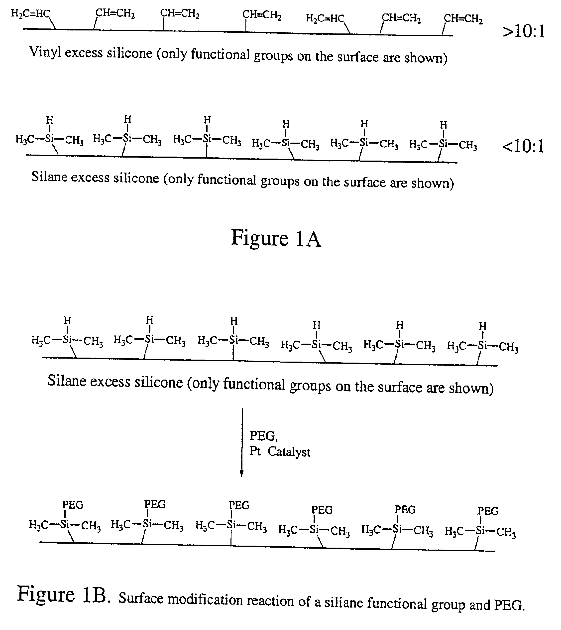
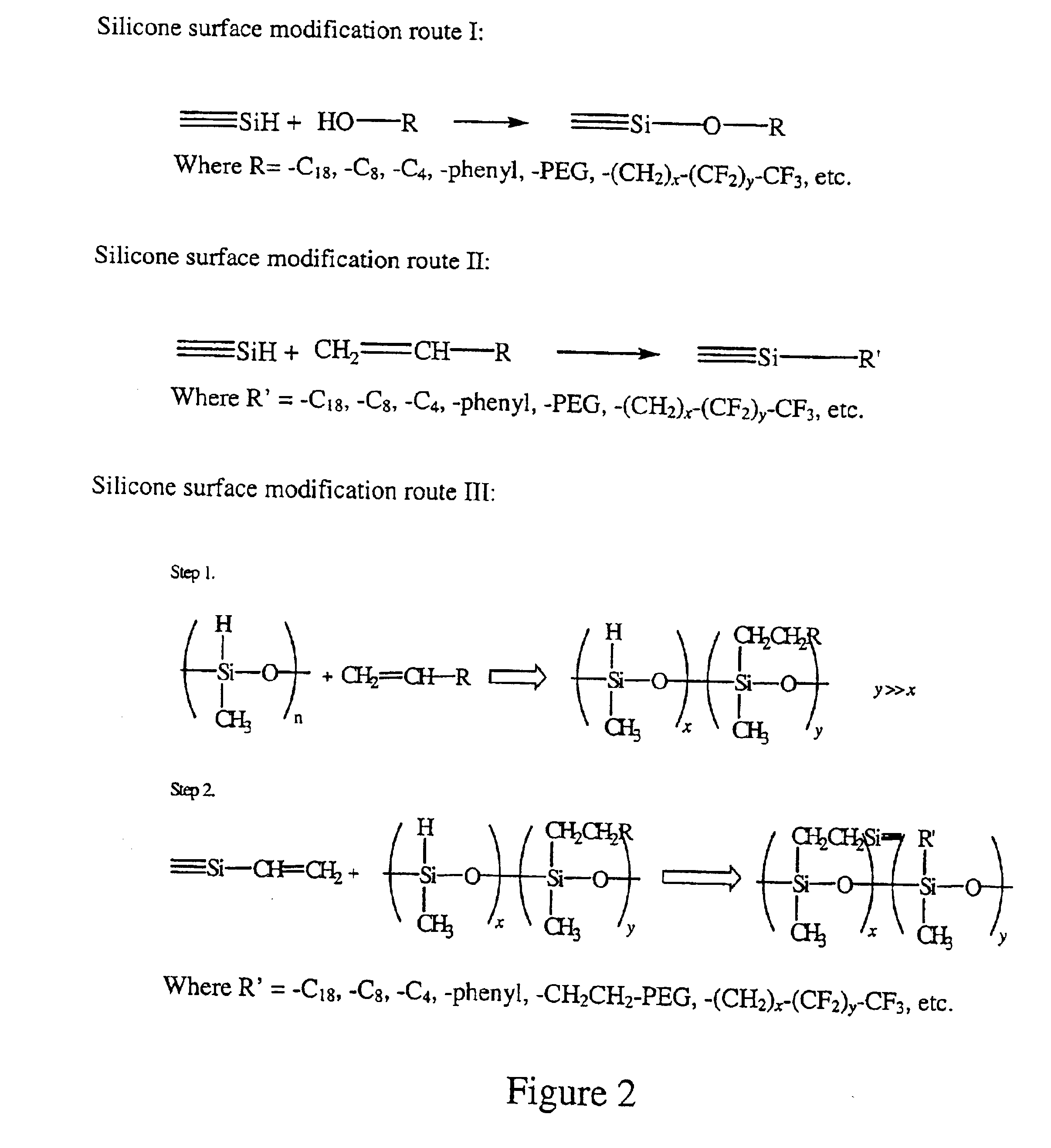
[0192]A 4:1 GE RTV silicone mixture was cured at 80° C. in a convection oven for 3 hrs. The excess hydrosilane groups from RTV 615B on the surface were utilized for polyethylene glycol grafting. An allyl-derived PEG, polyoxyethylene mono-allylether CH2═CHCH2O(CH2CH2O)16—H (AG-160) from Kowa was used for surface grafting. Platinum chloride catalyst, H2PtCl6 (Sigma-Aldrich), was used to catalyze the hydrosilylation reaction. The catalyst concentration used was in the range of 100˜1000 ppm (weight %) and the reaction time at 80° C. ranged from several minutes to hours, depending on the catalyst concentration. As expected, the higher the catalyst concentration, the shorter the reaction time was needed to achieve a desired degree of reaction. The molten AG-160 was used to carry out the reactions. The samples were then washed thoroughly with methanol and DI water in ultrasonic batch. The samples were then dried at 80° C. for 2 hrs. After the cleaning and drying, the top ˜1 μm of the PDMS ...

example 3

[0194]A 4:1 GE RTV 615 silicone mixture was cured at 80° C. in a convection oven for 3 hrs. The excess hydrosilane groups from RTV 615B on the surface were utilized for polyethylene glycol grafting. Allyl-derived PEG, polyoxyethylene mono-allylether CH2═CHCH2O(CH2CH2O)16—H (AG-160) from Kowa was used for surface grafting. The catalyst concentration is in the range of 100-1000 ppm (weight %) and the reaction time at 80° C. was from several minutes to several hours. Aqueous AG-160 solution (10 wt % of AG-160) was used to carry out the grafting reactions. FIG. 28 is an ATR-FTIR spectra of the PDMS samples with PEG grafting reactions carried out in water solution. The reaction trend is very similar to that of Example 1, but higher intensity of hydroxyl groups was observed at around 3400 cm−1. This may indicate the hydrolysis of surface siloxane groups.


PUM

PropertyMeasurementUnit
widthaaaaaaaaaa
Young's modulusaaaaaaaaaa

Abstract

The present invention is directed to a surface modified polymer comprising a surface which is covalently bonded to a surface modifying compound. Formation of the covalent bond between the polymer and the surface modifying compound is achieved by a reaction between an intrinsic functional group that is present in the polymer and the functional group of the surface modifying compound. By using a polymer having an intrinsic functional group, a separate surface activation step is avoided.

Description

CROSS-REFERENCES TO RELATED APPLICATIONS[0001]This application claims the benefit of U.S. Provisional Application No. 60 / 281,929, filed Apr. 6, 2001, which is incorporated herein by reference in its entirety.FIELD OF THE INVENTION[0002]The present invention relates to a surface modified polymer comprising an exterior surface containing a covalently bonded surface modifying compound and a bulk matrix comprising a reactive polymerizable functional group dispersed therein, and a method for using the same.BACKGROUND OF THE INVENTION[0003]Polymers are useful in a variety of applications, including fundamental research and biomedical applications such as solid phase diagnostics, drug delivery, biomaterials, and other areas. Unfortunately, many polymer materials are incompatible with a variety of reagents in many applications. For example, proteins and other biomolecules tend to adhere to hydrophobic surfaces, and therefore hydrophobic polymers may not be suitable in some applications wher...

Claims


Application Information

Patent Timeline
Patent Type & Authority Patents(United States)
IPC IPC(8): C08G77/38B32B3/20G01N37/00A61L27/00B01J20/285B01L3/00B81B1/00C08F257/02C08F263/04C08F265/04C08F279/02C08F287/00C08F291/00C08J5/12C08J7/12C08K5/00C08L83/04C08L101/00F04B43/04H01J49/04
CPCB01J20/285B01J20/327B01J20/3272B01L3/502707C08F257/02C08F263/04C08F265/04C08F279/02C08F287/00C08F291/00C08J5/12C08J7/12F04B43/043B01J20/286Y10T428/24661B01J2220/54B01L2200/12B01L2300/16B01L2300/163Y10T428/1393Y10T428/24744Y10T428/139F04B43/14Y10T428/249953Y10T428/249958Y10T428/249978Y10T428/31663Y10T428/31667B32B3/26
Inventor HUANG, JIANGXIAO, SHOUJUNUNGER, MARC A.
Owner FLUIDIGM CORP
Why Eureka
Try Eureka