High-yield activation of polymer surfaces for covalent attachment of molecules

Inactive Publication Date: 2007-08-23
THE TRUSTEES FOR PRINCETON UNIV
View PDF0 Cites 57 Cited by
  • Summary
  • Abstract
  • Description
  • Claims
  • Application Information

AI Technical Summary

Benefits of technology

[0019] The method of the present invention thus provides high yield coatings on polymer surfaces with the adhesion properties of physical de

Problems solved by technology

Adjustment of the surface properties of polymers such as those from which preformed polymeric therapeutic devices are formed, has proven problematic because those polymers most often used as biomaterials are resistant to specific surface treatments.
To circumvent this problem, polymer scaffold materials have been prepared by blending, copolymerization, or physical treatment, but these methods can resu

Method used


Image

  • High-yield activation of polymer surfaces for covalent attachment of molecules
  • High-yield activation of polymer surfaces for covalent attachment of molecules
  • High-yield activation of polymer surfaces for covalent attachment of molecules

Examples


example 1

Preparation of RGD-Modified Nylon Substrate

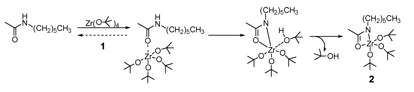
[0129] Activated nylon surface 4 was prepared by first casting films of 3 (nylon 6 / 6; (R═(CH2)4CO; R′═(CH2)6NH) from 0.1 mM formic acid solution on glass microscope slides that were rinsed copiously in Millipore® water, and evacuated at 10−2 torr for 3 hours. The coated slides were then placed in a deposition chamber that was equipped with two stopcocks for exposure either to vacuum or to vapor of zirconium tetra(tert-butoxide). The chamber was evacuated to 10−3 torr for 30 minutes, and slides of 3 were exposed to vapor of of zirconium tetra(tert-butoxide) (with external evacuation) for 30 seconds followed by 5 min exposure without external evacuation. This cycle was repeated twice, then followed by an additional 10 minutes of exposure without external evacuation. The chamber was then evacuated for 16 hours at 10−3 torr to ensure removal of excess zirconium tetra(tert-butoxide). The IR spectrum of polymer surface-bound Zr complex (4) showe...

example 2

Preparation of RGD-Modified Nylon Substrate

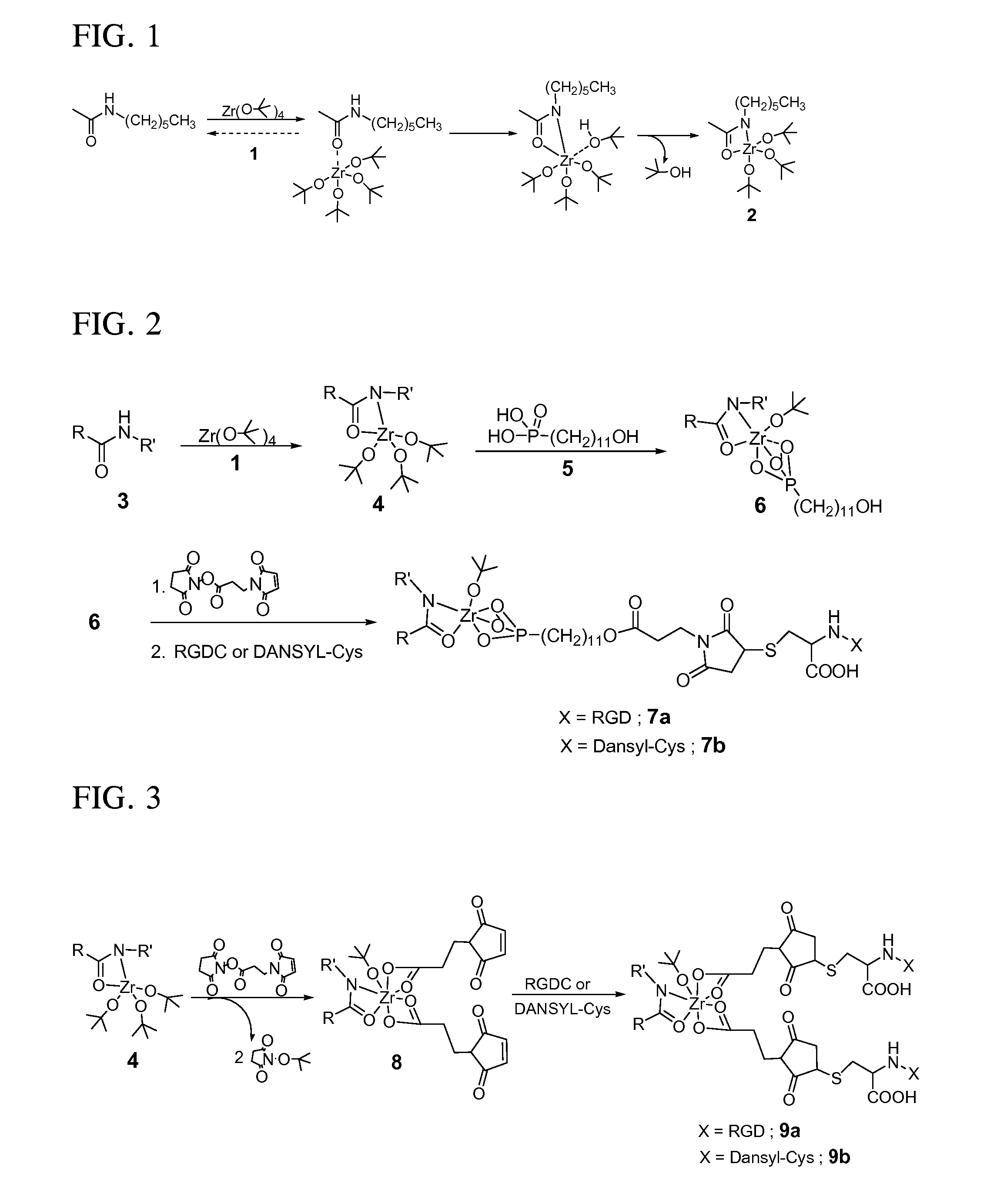
[0131] RGD-derivatized surface 9a (FIG. 3) was prepared by immersing a 4-coated slide in a 0.1 mM solution of 3-maleimidopropionic acid N-hydroxysuccinimide ester in dry acetonitrile for 16 hours to produce 8. Immersion of 8 in a 0.1 mM aqueous solution of RGDC at pH 6.5 for 24 hours produced 9a. The nylon-Zr surface complex was derivatized with the succinimide ester of 3-maleimidopropionic acid directly by transesterification to produce 8, which can result in either an RGDC or DANSYL-Cys-tethered surface (9a or 9b). Complexes 9a and 9b have a 1:2 ratio of zirconium to RGDC or DANSYL-Cys, respectively.

example 3

Preparation of DANSYL-Cys-Modified Nylon Substrate

[0132] Fluorescent molecule-labeled analogues 7b and 9b were prepared as described for 7a and 9a, but a 0.1 mM aqueous solution of N-(5-(dimethylamino)-1-naphthyl-sulfonyl)-cysteine (DANSYL-Cys) was used instead of RGDC (FIGS. 2 and 3).

[0133] To address the issue of solvent-induced polymer swelling, control films of 3 were prepared by soaking in 0.1 mM DANSYL-cys solution for 24 hrs. A calibration curve of fluorescence intensity versus concentration was measured for DANSYL-Cys solutions from 0.16 to 21 μM at pH 7.5 and pH 12.

[0134] Surface complex DANSYL content of 7b and 9b was quantified by immersion in water at pH 12 for 3 hours, which cleaves the Zr complexes from the surface, precipitates ZrO2, and releases fluorophore from 7b and 9b into solution. The amount of DANSYL surface-bound through Zr complexes 7b and 9b was measured to be 0.10 nmol / cm2 and 0.18 nmol / cm2, respectively. These amounts are consistent with the DANSYL:Zr ...


PUM

PropertyMeasurementUnit
Structureaaaaaaaaaa
Inductive effectaaaaaaaaaa

Abstract

Polymer surfaces coated with organometallic layers, wherein the organometallic layers and polymer surfaces have functional groups that react to bond the organometallic layer to the polymer surface with organometallic functional groups remaining unreacted for the subsequent covalent attachment of organic overlayers. Coating methods and coated articles are also disclosed.

Description

CROSS-REFERENCE TO RELATED APPLICATIONS [0001] The present application claims priority benefit under 35 U.S.C. §119(e) of U.S. Provisional Patent Application Nos. 60 / 775,127 filed Feb. 21, 2006 and 60 / 804,633 filed Jun. 13, 2006. The disclosures of both applications are incorporated herein by reference.BACKGROUND OF THE INVENTION [0002] The present invention relates to covalently binding organic materials to the surfaces of polymer substrates by functionalizing the surfaces with linker moieties containing transition metal complexes. In particular, the present invention relates to modifying polymer surfaces with organometallic compounds that have functional groups that react with functional groups of the polymer surface. The modified polymer surface can be further reacted with a compound, polymer or oligomer that contains functional groups that are reactive with functional groups of the organometallic compound that remain after reaction with the polymer surface. The present invention...

Claims


Application Information

Patent Timeline
IPC IPC(8): B32B27/00A61L33/00A61F2/06
CPCA61L27/14A61L27/28A61L27/30A61L27/38A61L27/50C08J2379/02A61L31/082C08H1/06C08J7/04C08J7/045C09J189/04A61L31/005Y10T428/31536Y10T428/31504A61P35/00A61P43/00C08J7/0423
Inventor SCHWARTZ, JEFFREYDENNES, T. JOSEPH
Owner THE TRUSTEES FOR PRINCETON UNIV
Why Eureka
Try Eureka