Low deformation electrolytic capacitor

Active Publication Date: 2006-02-28
PACESETTER INC
View PDF13 Cites 12 Cited by
  • Summary
  • Abstract
  • Description
  • Claims
  • Application Information

AI Technical Summary

Benefits of technology

[0013]The etched and formed anode foils are cut and the capacitor is assembled. The assembled capacitor is then vacuum-impregnated with an e

Problems solved by technology

Aluminum electrolytic capacitors tend to degrade with time.
Deformation of the aluminum oxide increases the leakage current of the capacitor, such that when one or more capacitors are used for shock delivery in an ICD, the first shock (after a hiatus) will have a significantly longer charge time.
Unfortunately, one cannot remove all of the water from the electrolyte, as it is needed for conduction, as well as for the formation of the cut edges of the aluminum foil after assembly.

Method used


Image

  • Low deformation electrolytic capacitor
  • Low deformation electrolytic capacitor
  • Low deformation electrolytic capacitor

Examples


Embodiment Construction

[0019]The present invention relates to electrolytic capacitors and, more particularly, to the reduction of water content within an electrolytic capacitor casing to reduce degradation of the capacitor over time.

[0020]Preferred embodiments are now described. While specific configurations and arrangements are discussed, it should be understood that this is done for illustrative purposes only. A person skilled in the relevant art will recognize that other configurations and arrangements can be used without departing from the spirit and scope of the invention. It will also be apparent to a person skilled in the relevant art that this invention can be employed in a variety of other devices and applications.

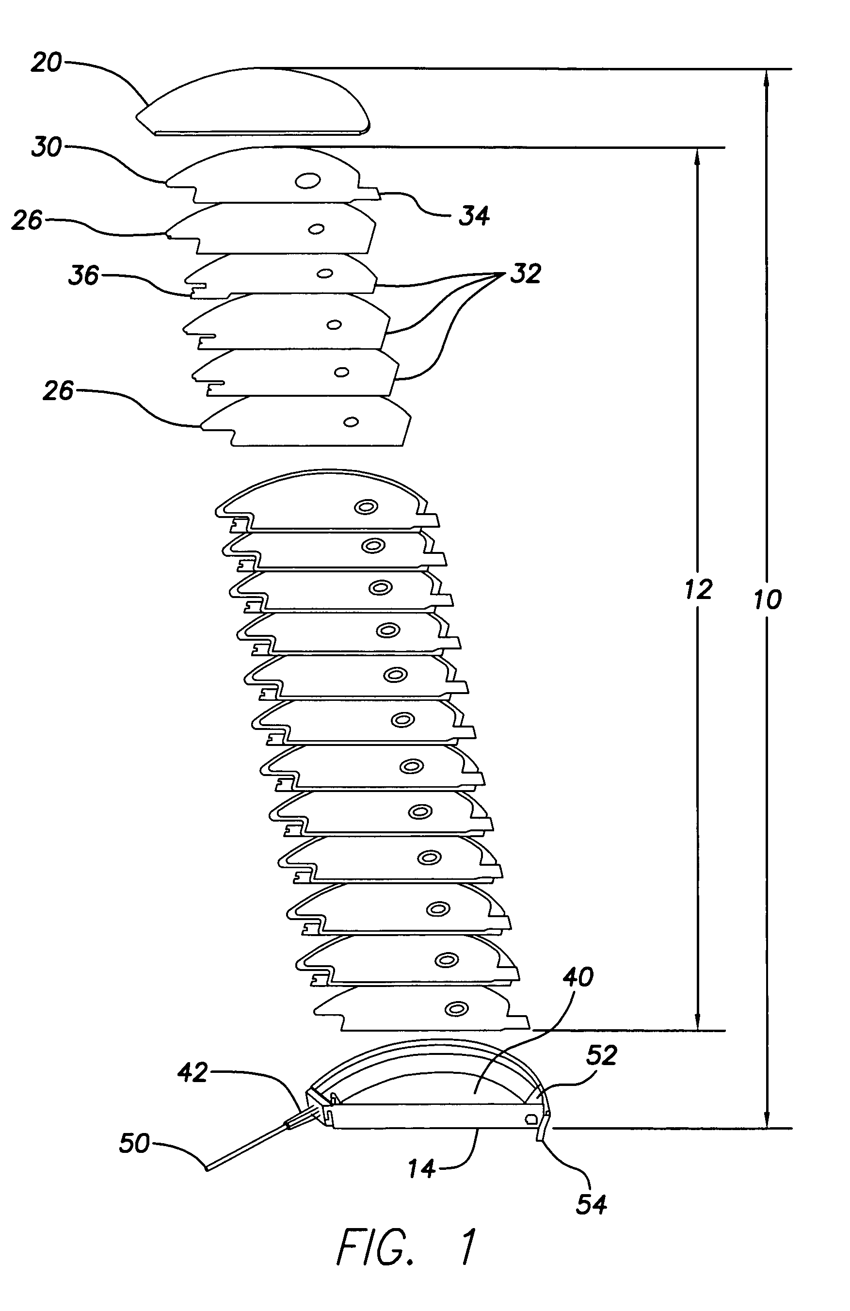
[0021]In one embodiment, an electrolytic capacitor is constructed of anode and cathode layers, stacked with a paper insulator or spacer between each layer, as shown in FIG. 1. Preferably, aluminum anode foil or other valve metal foil is employed, that has been etched and formed at volta...


PUM


Abstract

The present invention relates to electrolytic capacitors and, more particularly, to the reduction of water content within an electrolytic capacitor. Aluminum electrolytic capacitors tend to degrade with time. This is due, in part, to water in the electrolyte attacking the thin film of aluminum oxide (Al2O3) formed on the anode surface. Deformation of the aluminum oxide increases the leakage current of the capacitor, such that when one or more capacitors are used for shock delivery in an ICD, the first shock (after a hiatus) will have a significantly longer charge time. Unfortunately, one cannot remove all of the water from the electrolyte, as it is needed for conduction, as well as for the formation of the cut edges of the aluminum foil after assembly. According to the present invention, a desiccant material is used within an electrolytic capacitor casing to reduce the water content of a finished capacitor to below 1% by weight of the electrolyte. In a further embodiment, a moisture barrier layer is applied over the desiccant material, such that the desiccant material slowly absorbs moisture from the electrolyte, allowing for aging of the capacitor after assembly.

Description

FIELD OF THE INVENTION[0001]The present invention relates to electrolytic capacitors and, more particularly, to the reduction of water content within an electrolytic capacitor casing to reduce degradation of the capacitor over time.BACKGROUND OF THE INVENTION[0002]Compact, high voltage capacitors are utilized as energy storage reservoirs in many applications, including implantable medical devices. These capacitors are required to have a high energy density since it is desirable to minimize the overall size of the implanted device. This is particularly true of an Implantable Cardioverter Defibrillator (ICD), also referred to as an implantable defibrillator, since the high voltage capacitors used to deliver the defibrillation pulse can occupy as much as one third of the ICD volume.[0003]An ICD is a medical device that is implanted in a patient to monitor electrical activity of the heart and to deliver appropriate electrical and / or drug therapy, as required. ICDs include, for example, ...

Claims


Application Information

Patent Timeline
IPC IPC(8): H01G9/00A61N1/18H01G9/04
CPCH01G9/08H01G2/12A61N1/3968
Inventor KROLL, MARK W.STRANGE, THOMAS F.
Owner PACESETTER INC
Why Eureka
Try Eureka