
Boost rectifier with half-power rated semiconductor devices

a semiconductor device and boost rectifier technology, applied in the direction of electric variable regulation, process and machine control, instruments, etc., can solve the problems of increasing the cost of switching devices, reducing the efficiency of switching devices, and introducing significant harmonic distortion to the ac power system of rectifiers, so as to achieve the reduction of the acoustic noise and losses across the input side inductors, less expensive devices, and the effect of reducing the ac power conversion ra

Active Publication Date: 2006-02-28
WISCONSIN ALUMNI RES FOUND
View PDF1 Cites 17 Cited by
  • Summary
  • Abstract
  • Description
  • Claims
  • Application Information

AI Technical Summary

Benefits of technology

The invention is a new type of rectifier that can deliver performance similar to a conventional full-rated rectifier but with reduced costs. The rectifier has half-controlled circuits that can use smaller devices, reducing the size and weight of the rectifier. The rectifier also has lower losses and noise, and can operate at higher frequencies. The invention can be used in AC isolation or non-isolated configurations, depending on the desired performance and cost. The efficiency of the rectifier is higher, and it can be used with a transformer or without one. Overall, the invention simplifies the design and operation of the rectifier and reduces the size and cost of the components needed for the rectifier.

Problems solved by technology

While rectifiers formed of passive diodes are inexpensive and relatively reliable, such rectifiers can introduce significant harmonic distortion to the AC power system to which the rectifiers are connected.
The total harmonic distortion (THD) introduced by such diode rectifiers may not satisfy current standards and regulations such as the IEEE 519 standard.
A disadvantage of such active rectifiers is that the switching devices are much more expensive than passive diodes, particularly since each active switch must be capable of handling the full rated current and voltage of the system.
However, the price to be paid is higher THD and the presence of low order even harmonics on both the AC side and the DC side.
Thus, both the system efficiency and the performance are degraded as compared to the full active bridge.
However, appreciable THD still remained which was far from satisfactory given the IEEE 519 standards.
In addition, a lagging power factor command may not suit all rectifier loads and, more typically, a unity power factor interface is preferred or required.
Because the phase currents will contain appreciable lower order harmonics in a conventional three-phase half-controlled rectifier circuit as compared to a fully controlled rectifier circuit, the inductors will incur extra losses.
In addition, such systems may be prone to acoustic noise problems.

Method used


Image

  • Boost rectifier with half-power rated semiconductor devices
  • Boost rectifier with half-power rated semiconductor devices
  • Boost rectifier with half-power rated semiconductor devices

Examples


Embodiment Construction

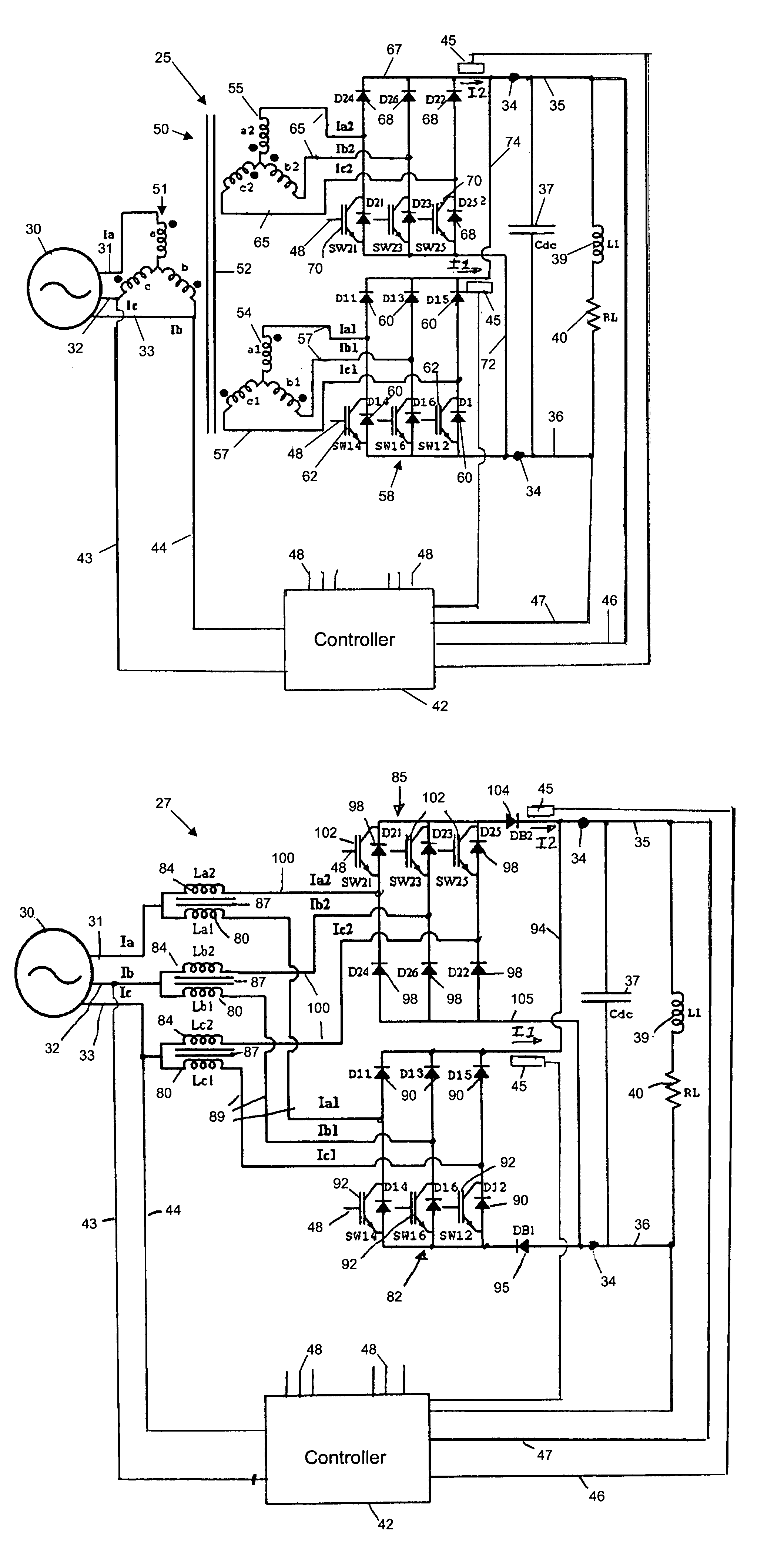
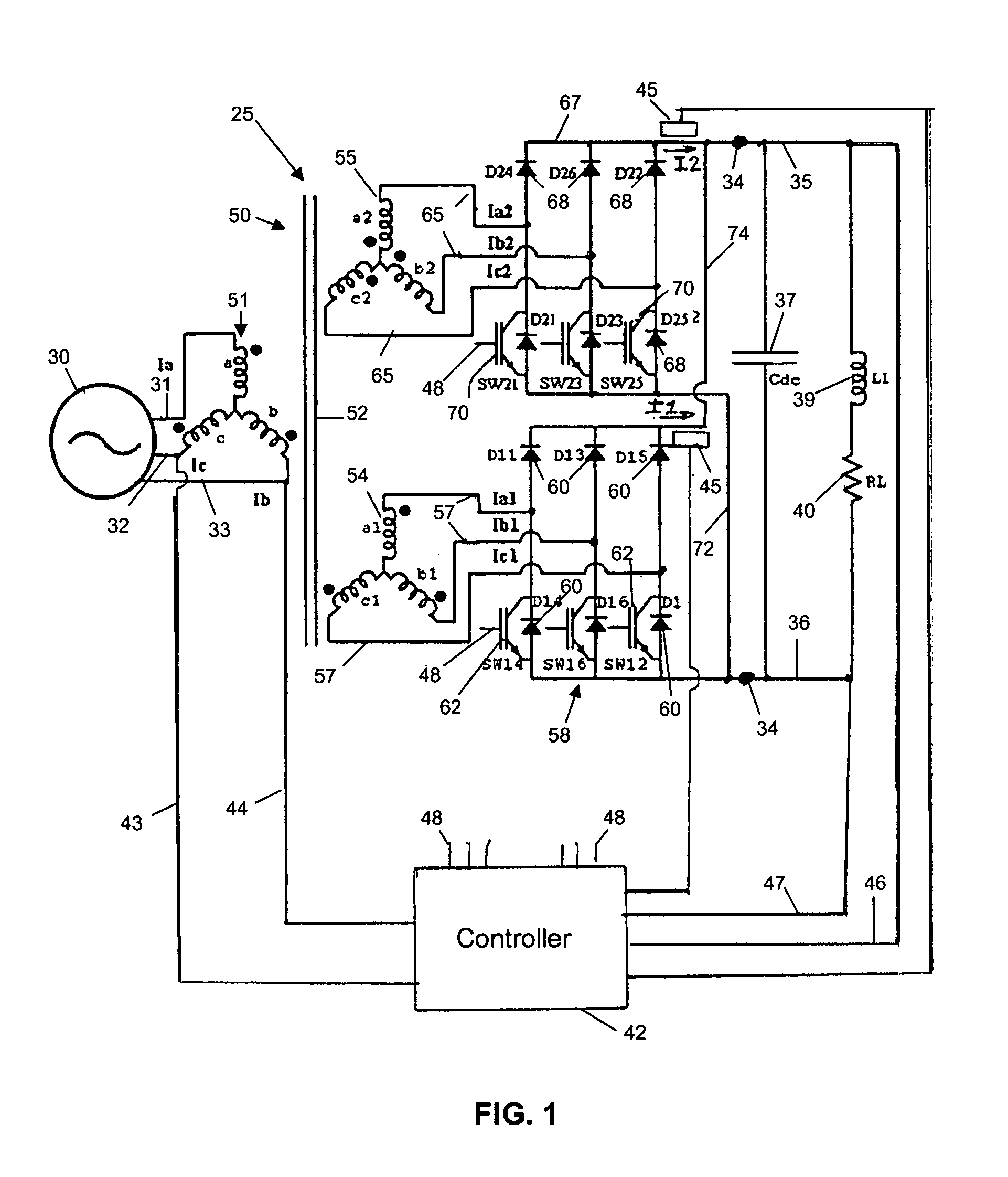
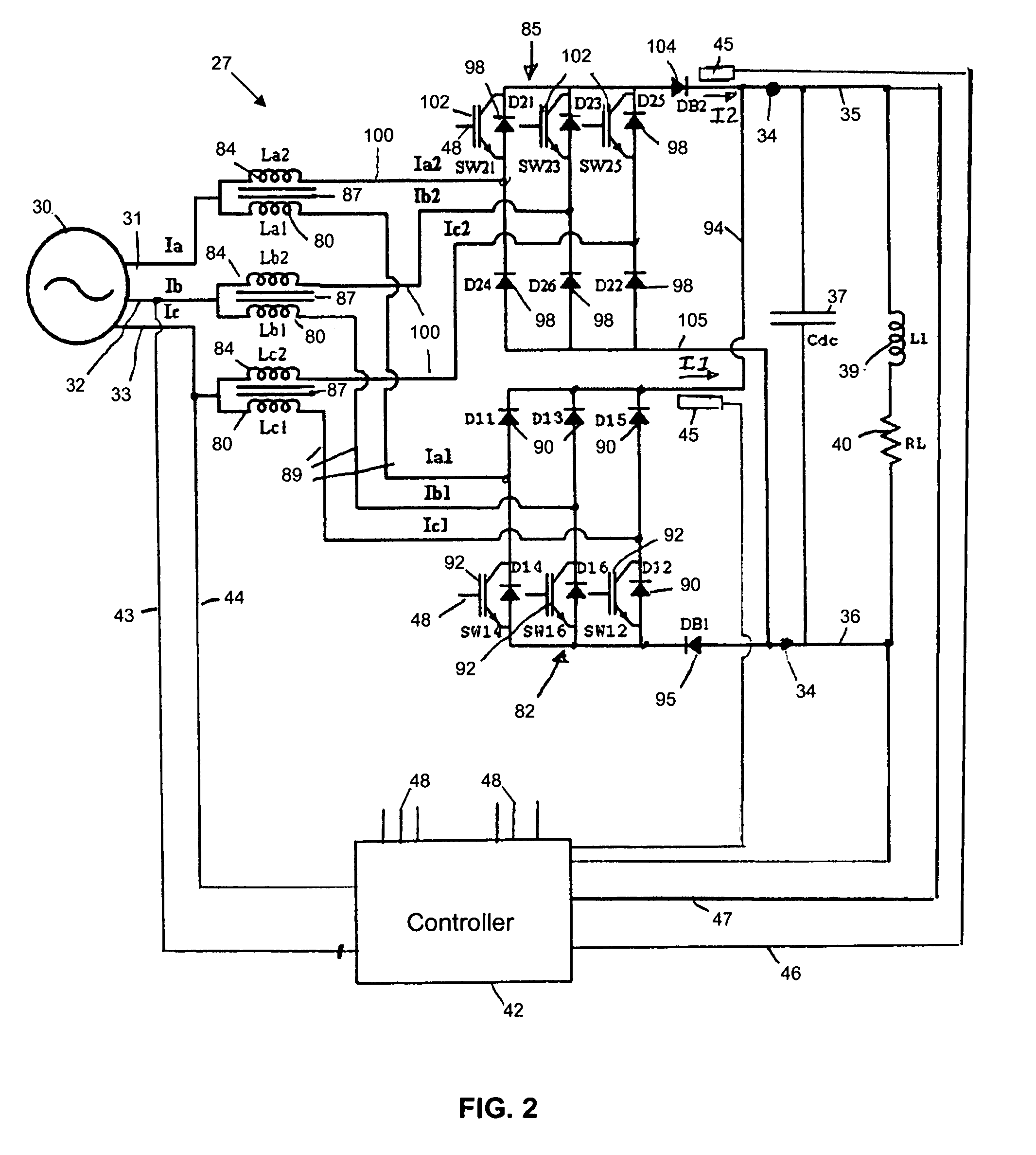
[0034]The rectifier of the present invention may be implemented in three-phase AC systems, and with and without AC side transformer isolation. For purposes of illustrating the principles of the invention, a three-phase boost rectifier in accordance with the invention having AC side transformer isolation is shown generally at 25 in FIG. 1, and a three-phase boost rectifier in accordance with the invention without AC side isolation is shown generally at 27 in FIG. 2. The principles of operation of the boost rectifiers 25 and 27 are essentially similar. A three-phase AC source 30 (e.g., AC power mains or a generator) provides three-phase AC power on rectifier input lines 31, 32 and 33, and each of the rectifiers 25 and 27 provide DC output power at rectifier output terminals 34 connected to DC bus lines 35 and 36 which have a DC bus capacitor 37 connected between them. The output terminals 34 may be discrete connectors but may also be, for example, conductors connected integrally with ...


PUM


Abstract

A rectifier has two half-controlled bridge rectifiers which are connected in parallel to provide DC power to DC bus lines. Each bridge rectifier receives AC power through inductances such as series inductors or an isolation transformer with a single primary and two secondaries. Each bridge rectifier has a full bridge of diodes, with active switching devices connected in parallel with half of the diodes in the bridge. The switching devices can be controlled to provide unity power factor at the AC input lines, allowing lower rated diodes and switching devices to be used.

Description

FIELD OF THE INVENTION[0001]This invention pertains generally to the field of electrical power conversion and particularly to controlled rectifiers.BACKGROUND OF THE INVENTION[0002]AC to DC electrical power rectifiers are used in a wide variety of applications, including power supplies for various types of electrical equipment and in motor drives. The simplest and least expensive type of rectifier uses a full or half bridge of diodes to rectify single-phase or three-phase AC input power to DC power. While rectifiers formed of passive diodes are inexpensive and relatively reliable, such rectifiers can introduce significant harmonic distortion to the AC power system to which the rectifiers are connected. The total harmonic distortion (THD) introduced by such diode rectifiers may not satisfy current standards and regulations such as the IEEE 519 standard. To address these limitations, rectifiers have been developed that include active switching devices, such as IGBT transistors, connec...

Claims


Application Information

Patent Timeline
Patent Type & Authority Patents(United States)
IPC IPC(8): H02M7/217H02M1/42H02M3/335H02M7/219
CPCH02M1/4216H02M7/219Y02B70/126H02M2001/0077H02M1/0077H02M1/0085Y02B70/10
Inventor PANDA, DEBIPRASADLIPO, THOMAS A.
Owner WISCONSIN ALUMNI RES FOUND
Learn More