Mask for improving lithography performance by using multi-transmittance photomask

a photomask and multi-transmittance technology, applied in the field of semi-tone photomasks, can solve the problems of complex and expensive, alignment problems, and possible and achieve the effects of improving critical dimension uniformity, improving photolithography performance, and improving iso-to-dense bias and edge-to-dense bias issues

Active Publication Date: 2006-03-07
MACRONIX INT CO LTD
View PDF3 Cites 6 Cited by
  • Summary
  • Abstract
  • Description
  • Claims
  • Application Information

AI Technical Summary

Benefits of technology

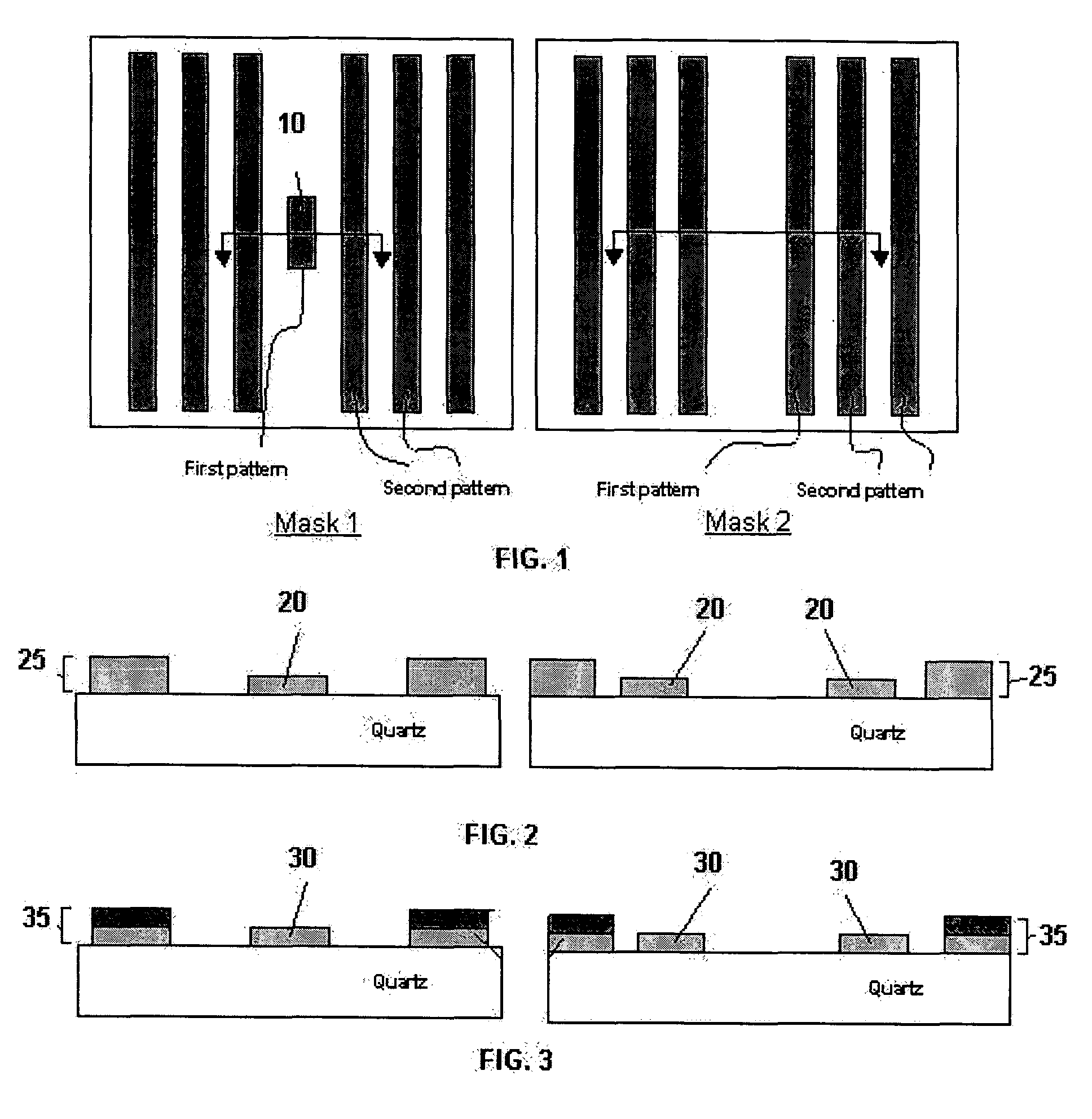
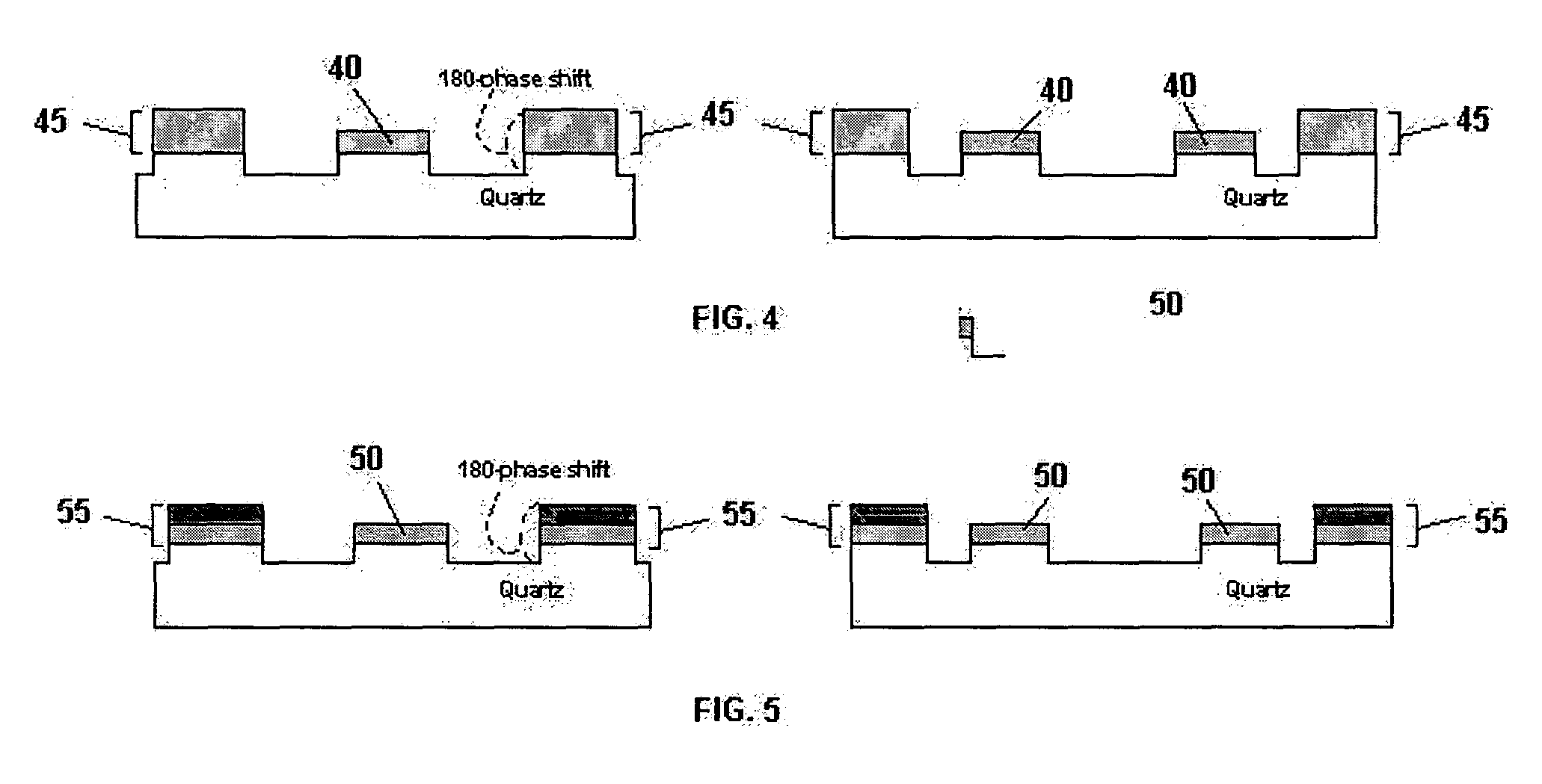
[0013]An apparatus for improving photolithography performance by using a multi-transmittance mask, and in accordance with certain aspects of the invention, by using a multi-transmittance halftone type phase shift photomask (HTPSM), is provided. The mask comprises a transparent substrate, a first pattern and a second pattern formed on the transparent substrate, wherein the second pattern is larger (e.g., longer) or denser than the first pattern, and a transmittance of the first pattern is higher than a transmittance of the second pattern. Iso-to-dense bias and edge-to-dense bias issues may be improved through use of the multi-transmittance masks of the present invention which in turn may provide an improved critical dimension uniformity and / or an improved common window. Accordingly, various implementations of the present invention may provide at least one of a reduced iso-to-dense bias, a reduced edge-to-dense bias, a reduced line end shortening, an improved critical dimension uniformity, and an improved or enlarged common window.

Problems solved by technology

If there are two patterns with different sizes or different densities on the same mask, line end shortening (LES), corner rounding, iso-to-dense bias and edge-to-dense bias issues may occur on the images translated to the photoresist from the mask.
Since this method needs two masks and two exposure steps, however, it can be complex and expensive.
In addition, alignment issues may arise with the use of two masks.
As dimensions shrink and line density increases, however, even SRAFs may be too large to fit within a given pattern to effectively reduce for example line end shortening and iso-to-dense bias.

Method used


Image

  • Mask for improving lithography performance by using multi-transmittance photomask
  • Mask for improving lithography performance by using multi-transmittance photomask
  • Mask for improving lithography performance by using multi-transmittance photomask

Examples


Embodiment Construction

[0026]Reference will now be made in detail to the presently preferred embodiments of the invention, examples of which are illustrated in the accompanying drawings. Wherever possible, the same or similar reference numbers are used in the drawings and the description to refer to the same or like parts. It should be noted that the drawings are in simplified form and are not to precise scale. In reference to the disclosure herein, for purposes of convenience and clarity only, directional terms, such as, top, bottom, left, right, up, down, over, above, below, beneath, rear, and front, are used with respect to the accompanying drawings. Such directional terms should not be construed to limit the scope of the invention in any manner.

[0027]Although the disclosure herein refers to certain illustrated embodiments, it is to be understood that these embodiments are presented by way of example and not by way of limitation. The intent of the following detailed description, although discussing exe...


PUM

PropertyMeasurementUnit
transmittanceaaaaaaaaaa

Abstract

Materials and methods for fabricating multi-transmittance halftone phase shift masks (HTPSM) are disclosed. The masks include patterns having regions of different transmittance for the purpose of reducing one or more of line edge shortening, iso-to-dense bias, and edge-to-dense bias. The masks employ at least one halftone material in forming the patterns that have different transmittances. Regions of denser or longer lines are constructed to have a lower transmittance than regions of isolated lines. The patterns may include a single halftone material of different thicknesses for different regions or may include two halftone materials applied singly and doubly to different regions.

Description

BACKGROUND OF THE INVENTION[0001]1. Field of the Invention[0002]The present invention relates generally to semiconductor manufacturing and, more particularly, to halftone photomasks.[0003]2. Description of Related Art[0004]One of the processing steps used during a semiconductor manufacturing process is photolithography. Photolithography is implemented numerous times during the manufacturing process and is one of the more important as well as one of the more limiting processes for determining a maximum density and final reliability of the integrated circuits. Photolithography can be particularly important in positioning the transistors, interconnect layers and via and in ensuring their uniformity.[0005]A typical photolithographic process is implemented by depositing onto a working surface, by means such as a spinner, a layer of photosensitive resist that can be patterned by exposure to ultraviolet (UV) light or another radiation type. The working surface may be a semiconductor wafer,...

Claims


Application Information

Patent Timeline
Patent Type & Authority Patents(United States)
IPC IPC(8): G03F9/00G03C5/00G03F1/00
CPCG03F1/32
Inventor YANG, CHIH-CHENG
Owner MACRONIX INT CO LTD
Why Eureka
Try Eureka