
Multiple access method and system

a multi-access method and spreadspectrum technology, applied in multiplex communication, using reradiation, instruments, etc., can solve the problems that conventional radio receivers cannot detect these signals, and achieve the effects of reducing the effect of multi-path fading and interference, reducing the required transmission power, and reducing interference to other systems

Inactive Publication Date: 2006-03-07
DEPARTMENT 13 INC
View PDF21 Cites 296 Cited by
  • Summary
  • Abstract
  • Description
  • Claims
  • Application Information

AI Technical Summary

Benefits of technology

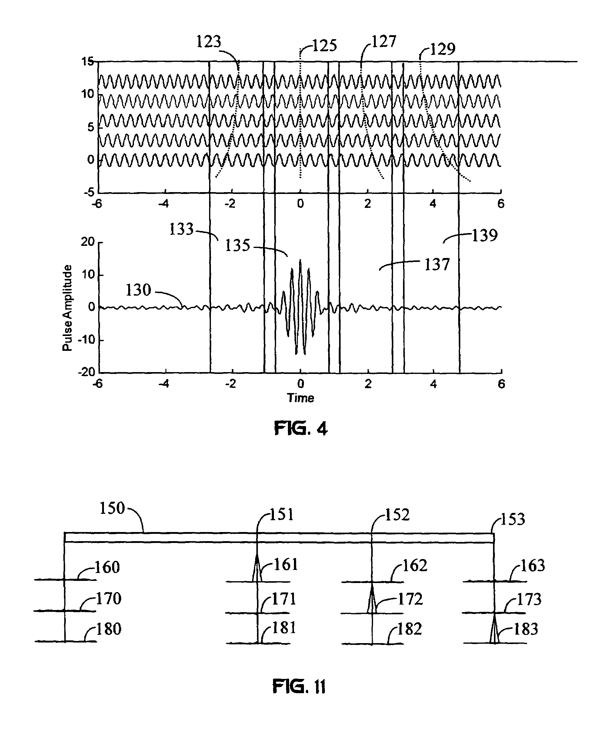
[0017]Because the carriers exist within the time interval where superposition yields a negligible signal level, it can be concluded that the pulse exists in a different phase space. This phase space is defined as a time (phase) offset between the carriers. The offset enables the pulse to be observed in a specific time interval. A receiver tuned to multiple phase spaces can generate multiple samples of the CIMA signal. Thus, CIMA enables signals to be processed simultaneously as both low and high data-rate signals. This mitigates the multipath problems inherent in both classes of signals and enables the system to function with substantially reduced signal power levels. Furthermore, if the CIMA carriers are pulse-amplitude modulated such that the superposition does not result in a pulse in zero-phase space, then the CIMA signals are visible only to CIMA receivers tuned to a nonzero-phase space. Conventional radio receivers can not detect these signals.
[0021]An objective of the invention is to reduce the effects of multipath fading and interference. A consequence of this objective is the reduction in required transmission power.
[0022]Another objective is to provide secure communications by creating transmissions that are difficult to intercept because they are nearly impossible to detect. The low power requirements of the carriers and the transmission of the carriers in nonzero-phase spaces accomplish this.
[0023]Another objective of the invention is to reduce interference to other systems and minimize the susceptibility of the communication system to all types of radio interference.
[0024]Another objective of the invention is to minimize and compensate for co-channel interference that occurs when the communication system serves multiple users.

Problems solved by technology

Conventional radio receivers can not detect these signals.

Method used


Image

  • Multiple access method and system
  • Multiple access method and system
  • Multiple access method and system

Examples


Embodiment Construction

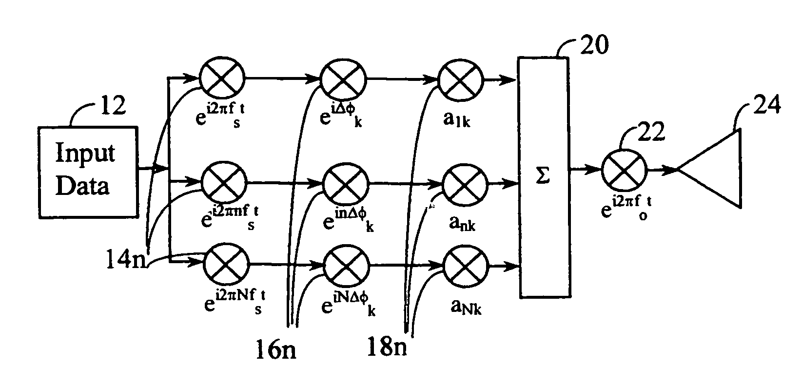
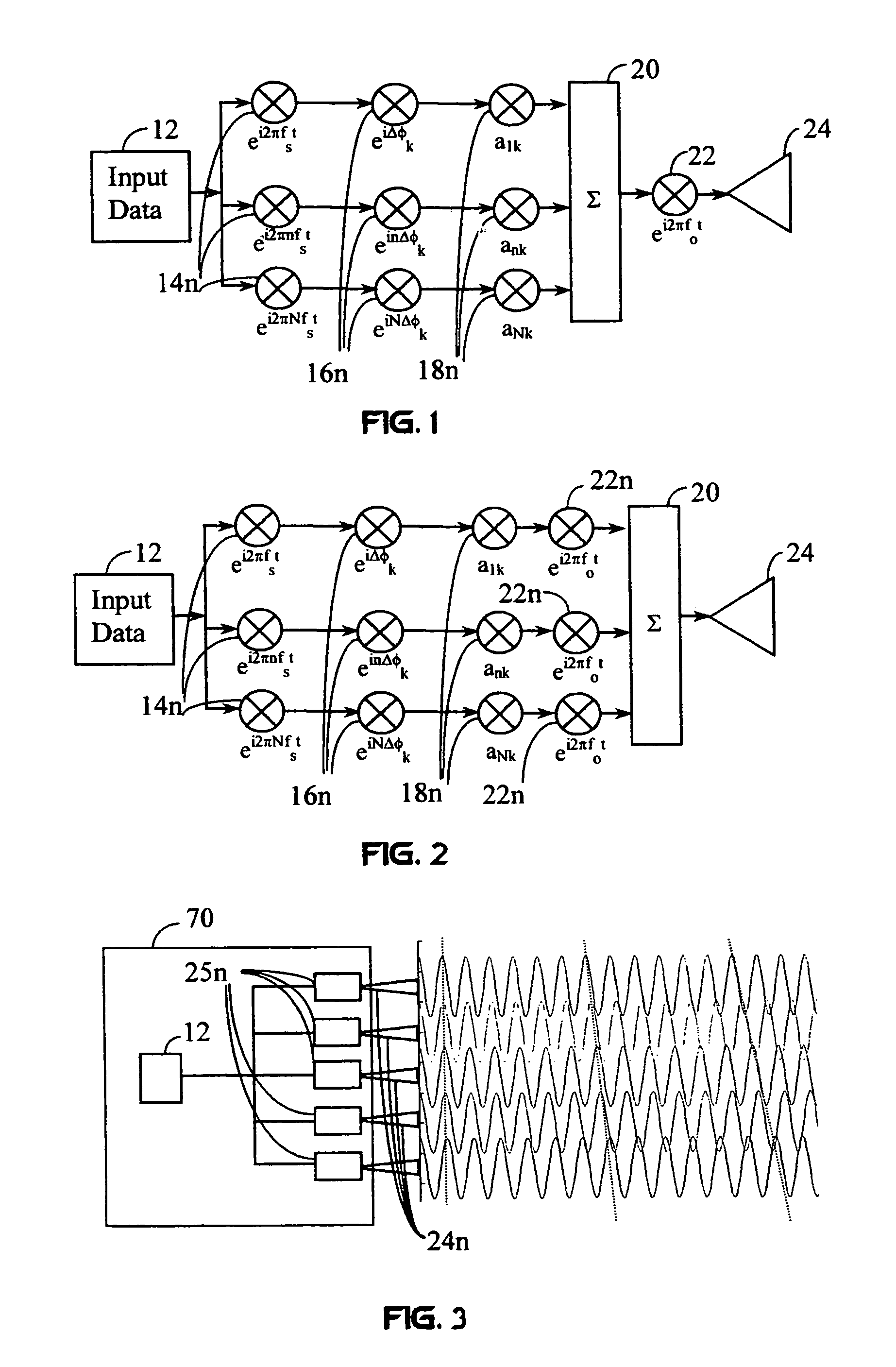
[0041]FIG. 1 shows a flow diagram of a CIMA transmitter that converts a baseband information signal for a single user k to a CIMA signal for transmission. Data received from an input data source 12 modulates a number N of CIMA carriers, which have different carrier frequencies. This modulation occurs at a plurality of carrier mixers 14n. In this case, the frequencies of the CIMA signals are incrementally spaced by a shift frequency fs. However, non-uniform spacing of the frequencies may also be used to achieve specific benefits described in U.S. patent application Ser. No. 09 / 022,950, which is incorporated herein by reference. The carrier frequencies are typically chosen to be orthogonal to each other: ∫0TC⁢cos⁡(ωi⁢t+ϕi)⁢cos⁡(ωj⁢t+ϕj)⁢⁢ⅆt=0

where Tc is the chip duration, ωi and ωj are the ith and jth carrier frequencies, and φi and φj are arbitrary phases. A signal in the jth frequency band does not cause interference in the ith frequency band. However, orthogonality of the waveforms...


PUM


Abstract

A wireless communication system transmits data on multiple carriers simultaneously to provide frequency diversity. Carrier interference causes a narrow pulse in the time domain when the relative phases of the multiple carriers are zero. Selection of the frequency separation and phases of the carriers controls the timing of the pulses. Both time division of the pulses and frequency division of the carriers achieves multiple access. Carrier interferometry is a basis from which other communication protocols can be derived. Frequency hopping and frequency shifting of the carriers does not change the pulse envelope if the relative frequency separation and phases between the carriers are preserved. Direct sequence CDMA signals are generated in the time domain by a predetermined selection of carrier amplitudes. Each pulse can be sampled in different phase spaces at different times. This enables communication in phase spaces that are not detectable by conventional receivers. The time-dependent phase relationship of the carriers provides automatic scanning of a beam pattern transmitted by an antenna array. In waveguide communications, the carrier frequencies and phase space may be matched to the chromatic dispersion of an optical fiber to increase the capacity of the fiber.

Description

[0001]This is a 371 of PCT application Ser. No. PCT / US99 / 02838, filed Feb. 10, 1999, which is a continuation-in-part of U.S. patent application Ser. No. 09 / 022,950, filed Feb. 12, 1998, now U.S. Pat. No. 5,955,992.FIELD OF THE INVENTION[0002]The present invention relates to a novel multicarrier spread-spectrum protocol for wireless and waveguide communications and radar.BACKGROUND OF THE INVENTION[0003]Multipath fading is the fluctuation in a received signal's amplitude. It is caused by interference between two or more versions of the transmitted signal that arrive at a receiver at different times. This interference results from reflections from the ground and nearby structures. The amount of multipath fading depends on the intensity and propagation time of the reflected signals and the bandwidth of the transmitted signal. The received signal may consist of a large number of waves having different amplitudes, and phases, and angles of arrival. These components combine vectorally at ...

Claims


Application Information

Patent Timeline
Patent Type & Authority Patents(United States)
IPC IPC(8): H04B1/69H04L27/00G01S13/28H04B1/7115H04B1/717H04J13/00H04L1/04H04L27/26
CPCH04B1/7174H04B7/0697H04B7/12H04J13/0077H04L27/2697H04J14/0298H04L1/04H04L27/2637H04L5/0021H04J14/02H04B1/7115
Inventor SHATTIL, STEVEN J.
Owner DEPARTMENT 13 INC
Learn More