Body fluid flow control method and device

a body fluid and flow control technology, applied in the field of implantable medical devices, can solve the problems of inconvenient use, difficulty in controlling the device, and inability to meet the needs of patients, and achieve the effects of preventing damage to the canal, reducing trauma, and reducing costs

Inactive Publication Date: 2006-03-14
PRECISION MEDICAL DEVICES INC
View PDF29 Cites 104 Cited by
  • Summary
  • Abstract
  • Description
  • Claims
  • Application Information

AI Technical Summary

Benefits of technology

[0026]Another aspect of the invention includes an implantable apparatus for controlling fluid flow in a host body. The implantable apparatus includes a constricting mechanism including a reciprocable member for selectively applying pressure to a canal of the host body in order to selectively constrict the canal. A pressure sensor is included for detecting the pressure applied by the reciprocable member to the canal. A feedback system is also included for altering movement of said reciprocable member in response to the pressure sensed by said pressure sensor in order to prevent damage to said canal.
[0027]The object and advantages of the implantable fluid flow control devices of the present invention permit implantation and use without severing the canal or vessel to be constricted. Moreover, because trauma is minimized with respect to the canal or vessel, and the devices of the present invention are relatively small, lightweight and made of corrosion-resistant material, such as durable plastics, titanium or stainless steel, the devices are suitable for use for extended periods of time to control fluid flow through numerous types of vessels to control, for example, urination, defecation, ejaculation, nutrition absorption for control of obesity, etc. Splitting the fluid flow control device and its control box also provides significant advantages. The surgery to implant the fluid flow control device is delicate and involved, whereas the surgery to implant the control box is much less involved as the control box may be implanted in an easily accessible place, just under the skin of the patient. Thus, when any part of the control box fails, the control box may be removed and replaced with a new control box without needing to adjust the fluid flow control device. The replacement of the control box does not therefore need to be done by a specialist surgeon, and may be performed in a large number of hospitals or even physicians offices under local anaesthetic. The surgery is thus much less traumatic for the patient and may be performed in a location that is convenient for the patient rather than in a hospital that is able to perform specialized urological surgeries.

Problems solved by technology

The cost and inconvenience to persons suffering from this condition are great.
However, control of this device is sometimes difficult and is often inconvenient.
Throughout the full range of the available treatment alternatives, the levels of efficacy, useful life, and complications vary greatly, with none of the current treatment alternatives being particularly effective in especially severe cases.

Method used


Image

  • Body fluid flow control method and device
  • Body fluid flow control method and device
  • Body fluid flow control method and device

Examples


Embodiment Construction

[0053]By way of illustrating and providing a more complete appreciation of the present invention and many of the attendant advantages thereof, the following detailed description is given concerning the novel implantable body fluid control device and uses thereof.

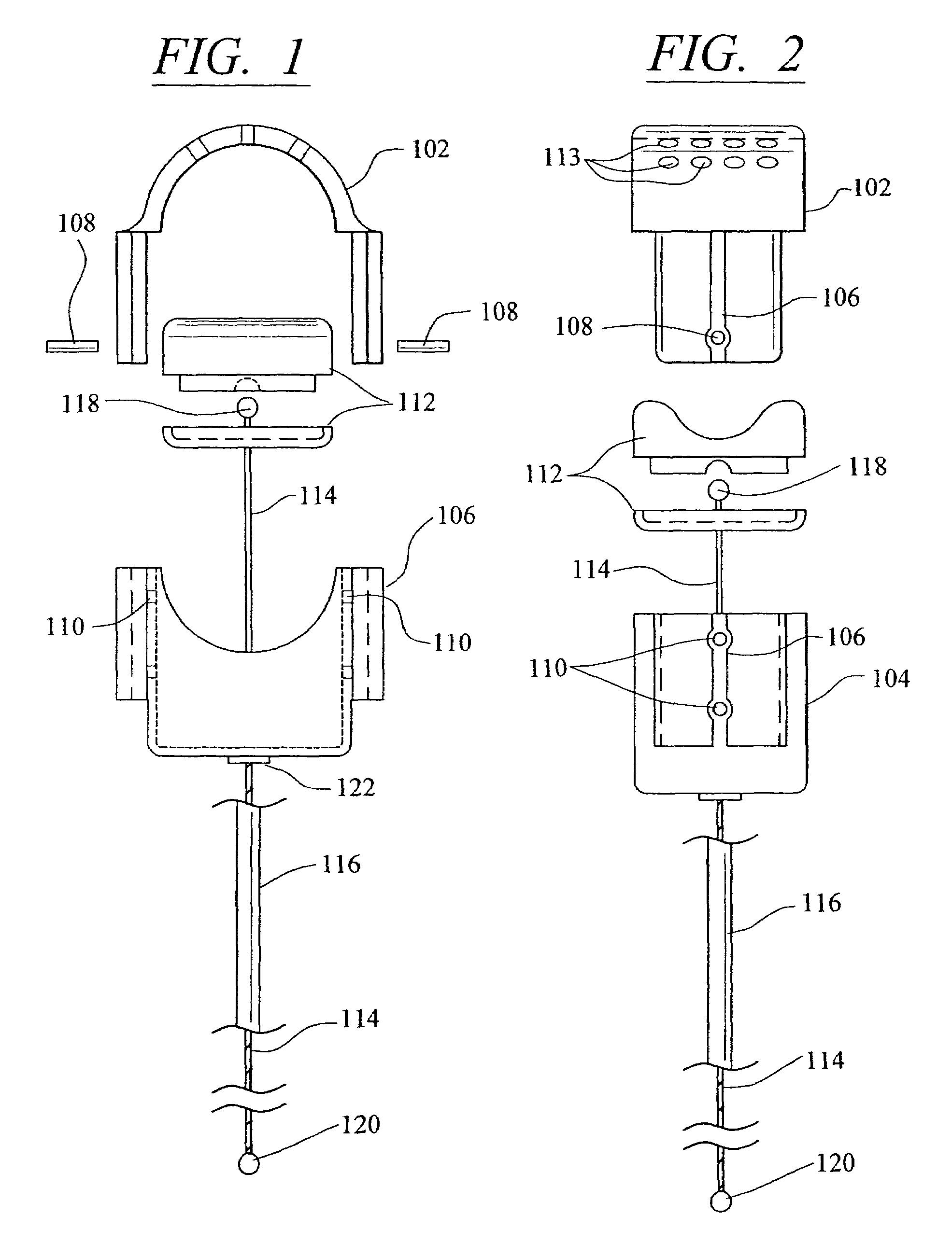
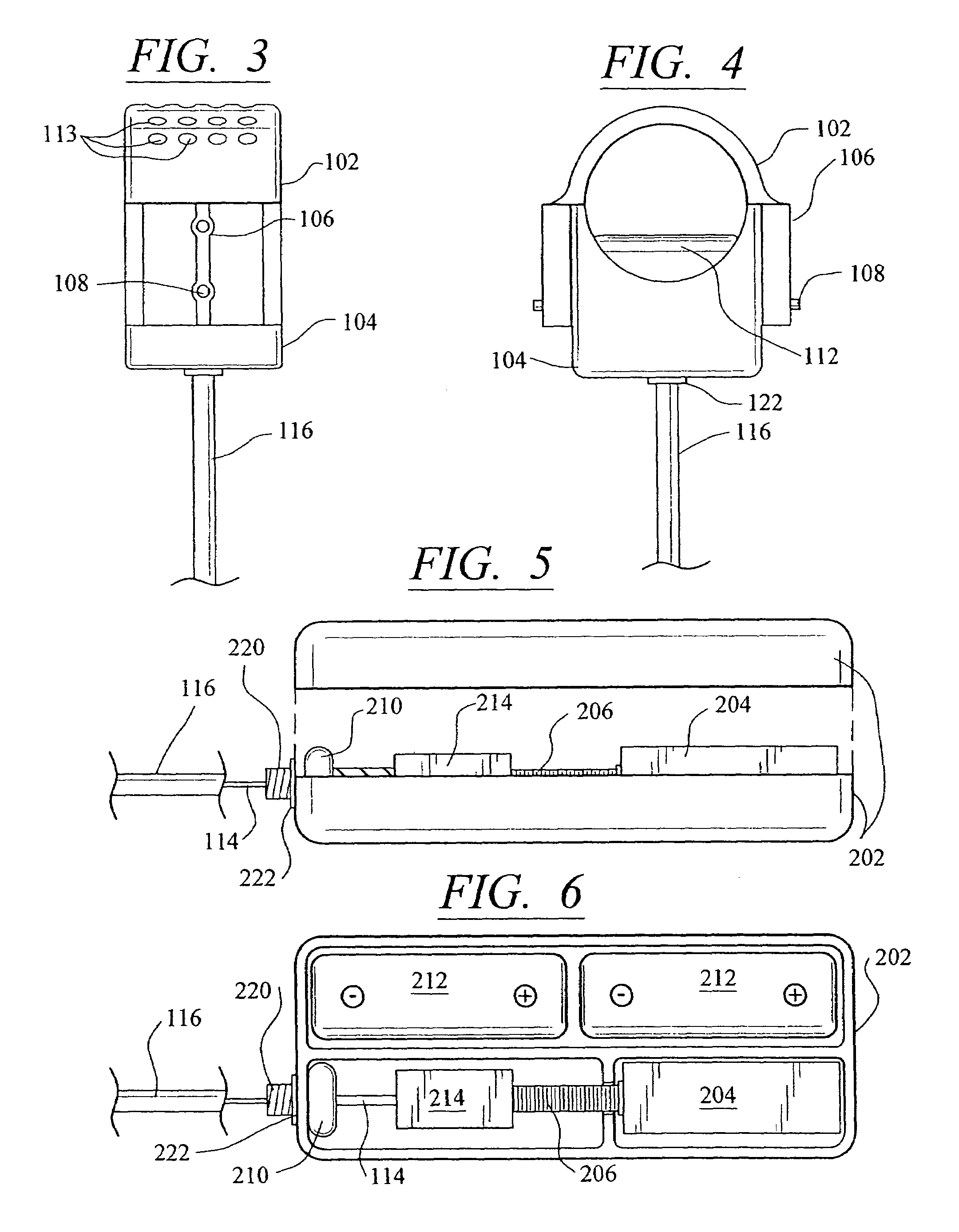
[0054]Referring now in more detail to the drawings, in which like numerals refer to like parts throughout several views, FIGS. 1–4 show a body fluid flow control device according to the present invention. The body fluid flow control device comprises a first engaging element 102 and a second engaging element 104. When the first engaging element 102 is coupled with the second engaging element 104, an inner diameter is formed which is suited for fitting around a host body canal, i.e., any tube or vessel V within the human or animal body, such as the urethra.

[0055]The body fluid flow control device also comprises a locking mechanism 106 for locking the first and second engaging elements 102 and 104 together. The locking mechanis...


PUM


Abstract

An implantable apparatus for controlling fluid flow within a host body includes a constricting member for allowing fluid flow within a body canal when in an open position, and for reducing fluid flow within a body canal when in an closed position. Remote telemetry can be used to operate the constricting member from a position outside the body. The constricting member can include a piston having at least two protrusions for contacting the vessel surface of the body canal. A fluid-operated member can receive fluid to reduce fluid flow within the body canal and expel fluid to allow fluid flow within the body canal. An actuating member is provided for operating the fluid-operated member between the open and closed positions. The actuating member has structure for flowing fluid into and out of the fluid-operated member. A control device is provided for operating the actuating member. An implantable drive mechanism for a constricting member or other medical device includes a sealed housing for implantation in a patient body, a drive magnet positioned within the housing, an actuator for moving the drive magnet, and a magnetically susceptible drive member positioned outside the housing such that movement of the drive magnet within the housing will move the drive member outside of the housing.

Description

CROSS-REFERENCE TO RELATED APPLICATIONS[0001]This is a continuation-in-part application of U.S. patent application Ser. No. 09 / 965,762, filed Sep. 28, 2001 now U.S. Pat. No. 6,689,046, which itself is a continuation-in-part application of U.S. patent application Ser. No. 09 / 676,336, filed Sep. 29, 2000 now U.S. Pat. No. 6,527,701;FIELD OF THE INVENTION[0002]The invention relates to an implantable medical device and a method for the control of fluid flow through a body host canal or vessel, such as a urethra.BACKGROUND OF THE INVENTION[0003]Incontinence is a condition wherein persons lose control over their voluntary urinary function. The condition can arise from various causes, which include a variety of related and unrelated diseases, aging, and deterioration of the voluntary urethra sphincter muscle. The cost and inconvenience to persons suffering from this condition are great. Several remedies exist that are known in the prior art. Among these, the most common are surgical correc...

Claims


Application Information

Patent Timeline
Patent Type & Authority Patents(United States)
IPC IPC(8): A61F2/02A61B17/08A61B17/00A61BA61F2/00A61F2/04A61F2/48A61F2/72
CPCA61F2/0036A61F2/004A61F2250/0002A61F2210/009A61F2/00A61F2/02
Inventor SAYET, PETER H.SUTHERLAND, LLOYD A.POLITANO, VICTOR
Owner PRECISION MEDICAL DEVICES INC
Why Eureka
Try Eureka