Method of making carbon nanotubes on a substrate

Inactive Publication Date: 2006-03-14
BATTELLE MEMORIAL INST
View PDF2 Cites 80 Cited by
  • Summary
  • Abstract
  • Description
  • Claims
  • Application Information

AI Technical Summary

Benefits of technology

[0011]The present invention further provides a method for making the filled carbon nanotubes on prepared substrates. The method includes the steps of depositing a growth catalyst onto a conductive substrate to form the prepared substrate, creating a vacuum within a vessel which contains the prepared substrate, flowing H2/inert (e.g. Ar) gas within the vessel

Problems solved by technology

Disadvantages of these separations between the carbon nanotubes include decreased nanotube capacity on the substrate and a decreased ability to maintain alignment as the nanotubes grow longer.
The

Method used


Image

  • Method of making carbon nanotubes on a substrate
  • Method of making carbon nanotubes on a substrate
  • Method of making carbon nanotubes on a substrate

Examples


example 1

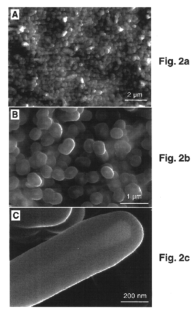
[0026]A number of conductive substrates were selected to investigate their effects on the formation of the filled carbon nanotubes. The formation of the filled nanotubes depends on the solubility of the iron (the catalyst) in the conductive substrate and the free energy of formation for the respective carbide phase. The conductive substrate materials selected included tantalum, silicon, and molybdenum. All of these materials can form stable carbides. Carbon nanotubes were deposited on the prepared substrates under the same growth conditions used for growth of carbon nanotubes using titanium conductive substrates. While dense arrays of filled carbon nanotubes were observed on tantalum conductive substrates similar to those shown in FIG. 2a, only curved hollow carbon nanotubes were formed on silicon conductive substrates. No carbon nanotubes were observed on molybdenum conductive substrates. For molybdenum conductive substrates, X-ray photoelectron spectrometry and backscattering elec...


PUM

PropertyMeasurementUnit
Temperatureaaaaaaaaaa
Lengthaaaaaaaaaa

Abstract

The present invention includes carbon nanotubes whose hollow cores are 100% filled with conductive filler. The carbon nanotubes are in uniform arrays on a conductive substrate and are well-aligned and can be densely packed. The uniformity of the carbon nanotube arrays is indicated by the uniform length and diameter of the carbon nanotubes, both which vary from nanotube to nanotube on a given array by no more than about 5%. The alignment of the carbon nanotubes is indicated by the perpendicular growth of the nanotubes from the substrates which is achieved in part by the simultaneous growth of the conductive filler within the hollow core of the nanotube and the densely packed growth of the nanotubes. The present invention provides a densely packed carbon nanotube growth where each nanotube is in contact with at least one nearest-neighbor nanotube. The substrate is a conductive substrate coated with a growth catalyst, and the conductive filler can be single crystals of carbide formed by a solid state reaction between the substrate material and the growth catalyst. The present invention further provides a method for making the filled carbon nanotubes on the conductive substrates. The method includes the steps of depositing a growth catalyst onto the conductive substrate as a prepared substrate, creating a vacuum within a vessel which contains the prepared substrate, flowing H2/inert (e.g. Ar) gas within the vessel to increase and maintain the pressure within the vessel, increasing the temperature of the prepared substrate, and changing the H2/Ar gas to ethylene gas such that the ethylene gas flows within the vessel. Additionally, varying the density and separation of the catalyst particles on the conductive substrate can be used to control the diameter of the nanotubes.

Description

CROSS REFERENCE TO RELATED APPLICATIONS[0001]This Application is a divisional of U.S. Ser. No. 09 / 333,876, filed Jun. 14, 1999, now U.S. Pat. No. 6,361,861.STATEMENT REGARDING FEDERALLY SPONSORED RESEARCH OR DEVELOPMENT[0002]This invention was made with Government support under Contract DE-AC0676RLO1830 awarded by the U.S. Department of Energy. The Government has certain rights in the invention.FIELD OF THE INVENTION[0003]The present invention relates generally to the synthesis of carbon nanotubes on substrates. More specifically, the invention relates to dense arrays of well-aligned carbon nanotubes filled with conductive filler synthesized on conductive substrates and a method for making these carbon nanotubes.BACKGROUND OF THE INVENTION[0004]Carbon nanotubes constitute a new class of materials with a broad range of potential applications. Their unique properties make carbon nanotubes ideal candidates for novel application in areas such as vacuum microelectronics, flat panel displ...

Claims


Application Information

Patent Timeline
IPC IPC(8): H01J9/02C23C26/00D01F9/12H01J1/30C01B31/02
CPCB82Y30/00B82Y40/00C01B31/0233C01B2202/08C01B2202/34C01B2202/36Y10T428/2918Y10S977/843Y10S977/842Y10S427/102Y10T428/2913Y10T428/12438Y10S977/742C01B32/162
Inventor GAO, YUFEILIU, JUN
Owner BATTELLE MEMORIAL INST
Why Eureka
Try Eureka