Charging circuit for secondary battery

a charging circuit and secondary battery technology, applied in electric power, electric vehicles, transportation and packaging, etc., can solve the problems of shortening the charging time compared with the constant-current/constant-voltage method, affecting the quality of secondary batteries, and affecting the performance of secondary batteries, so as to reduce manufacturing costs and high accuracy

Inactive Publication Date: 2006-03-14
RICOH KK
View PDF28 Cites 76 Cited by
  • Summary
  • Abstract
  • Description
  • Claims
  • Application Information

AI Technical Summary

Benefits of technology

[0034]According to the above-mentioned aspects of the present invention, the charging is completed by detecting, without a resistor, the charging current output from the constant-voltage circuit. Thus, there is no heat generation and no power loss due to the resistor. Accordingly, it is possible to detect the full charge state of the secondary battery with high accuracy.
[0035]In addition, according to the above-mentioned aspects of the present invention, in a case where the battery voltage of the secondary battery is lower than the predetermined voltage, it is possible to charge the secondary battery with a current having an amount suitable for such a case. Thus, it is possible to charge the secondary battery in an over-discharged state. Furthermore, the above-mentioned charging circuit can be realized while restraining the increase in the size of the circuit. Therefore, it is possible to reduce the manufacturing cost.

Problems solved by technology

However, when the lithium ion battery is overcharged, there is a possibility that the performance of the battery is degraded.
However, in the above-described first method, there is a problem in that the charging time becomes longer compared with the constant-current / constant-voltage method.
Thus, there is a problem in that noise occurs over a wide frequency band.
Thus, there is a problem in that electric power loss occurs.
Accordingly, there is another problem in that the electric power loss becomes greater, and at the same time, a complex circuit is required.
However, at the beginning of charging, the charging current is high and a sharp voltage drop results.
In addition, power loss due to the heat generation is also great.
However, by performing the constant-voltage charge, the current when charge complete is detected is small, and since the voltage drop across the resistor R1 is low, an input offset voltage of the operational amplifier A1 detecting the generated voltage is not negligible.
In other words, there is a problem in that the accuracy of detecting the charging current is deteriorated.
Further, there is also a problem in that, since operational amplifiers having a small offset voltage are expensive, the manufacturing cost increases when using them.
Furthermore, a problem occurs when a large current is supplied to the secondary battery at the beginning of charging in a case where the secondary battery is in an over-discharged state.
Accordingly, it is impossible for such a charging circuit to charge the secondary battery that is in an over-discharged state.

Method used


Image

  • Charging circuit for secondary battery
  • Charging circuit for secondary battery
  • Charging circuit for secondary battery

Examples


first embodiment

[0051]Next, a detailed description will be given of the present invention, with reference to the drawings.

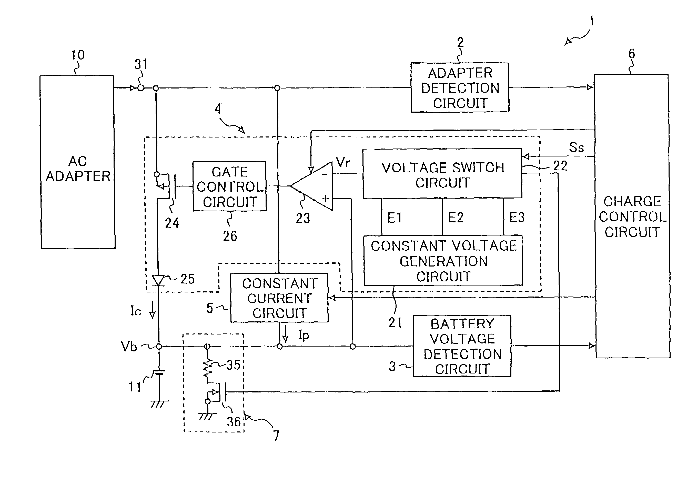
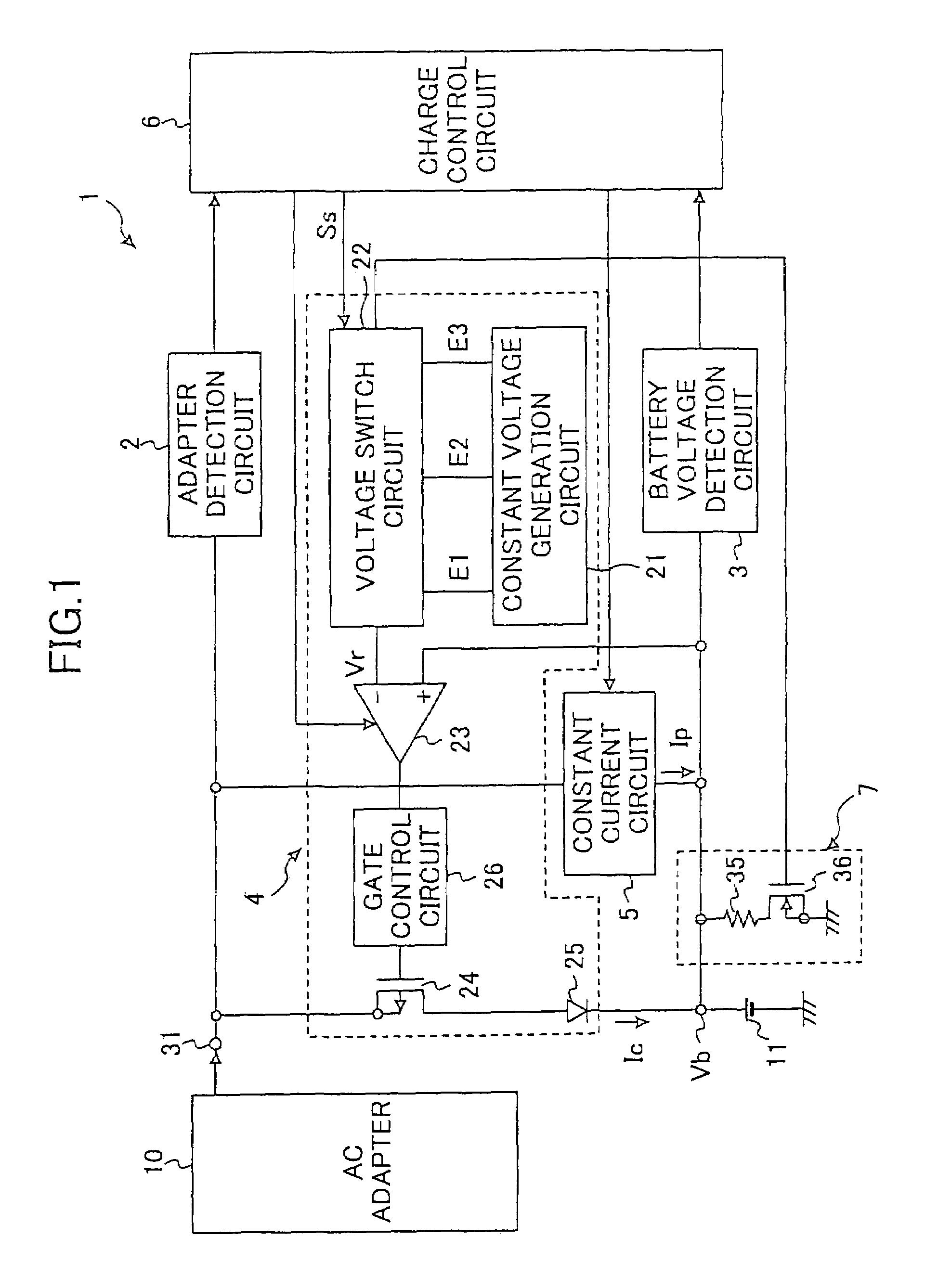
[0052]FIG. 1 is a diagram showing an example of the structure of a charging circuit for a secondary battery in a first embodiment of the present invention. It should be noted that FIG. 1 shows the example of the charging circuit for a lithium ion battery used for a mobile phone.

[0053]In FIG. 1, a charging circuit 1 for a secondary battery includes an adapter detection circuit 2 that outputs a predetermined signal when a power supply voltage from an AC adapter 10 that is a direct-current power source is equal to or higher than a predetermined value, a battery voltage detection circuit 3 that detects and outputs a positive voltage (hereinafter referred to as a “battery voltage”) Vb of a lithium ion battery 11 that is a secondary battery, and a constant-voltage circuit 4 that charges the lithium ion battery 11 at a constant-voltage.

[0054]Further, the charging circuit 1 includes a c...

second embodiment

[0080]In the following, a description will be given of the present invention, with reference to the drawings.

[0081]FIG. 5 is a diagram showing a charging circuit according to the second embodiment of the present invention. In FIG. 5, the charging circuit includes an AC adapter B10 that supplies a charging current, an adapter detection circuit 12 detecting that the AC adapter B10 is connected, a battery voltage detection circuit 16 that detects the voltage of a secondary battery 14, a constant-voltage circuit 18 that performs a constant-voltage charge on the secondary battery 14, a constant-current circuit 20 that supplies a constant-current to the secondary battery 14, a gate voltage detection circuit B22 that detects the voltage of a control terminal of a control transistor M1, a diode D1 that blocks a current flowing from the secondary battery 14 to the AC adapter B10, and a charge control circuit B24 that performs drive control of the constant-voltage circuit 18 and the constant-...

third embodiment

[0100]Further, in the charging circuit by using the constant-voltage generation circuit 42 that generates the reference voltage BE2, the gate voltage detection circuit B22 sets the voltage dropped from the voltage of the AC adapter B10 by the reference voltage BE2 equal to the gate voltage at which the PMOS transistor M1 is cut off. However, this is the same thing as to set the charge complete voltage equal to the gate voltage at which the pMOS transistor M1 is cut off, by using the constant-voltage generation circuit that generates the charge complete voltage. In addition, by using the constant-voltage generation circuit 46 that generates the reference voltage BE4, the charge current control circuit 50 sets the voltage dropped from the voltage of the AC adapter B10 by the reference voltage BE4 equal to the gate voltage of the pMOS transistor M1 that outputs the predetermined constant current. However, this is the same thing as to set, by using the constant-voltage generation circu...


PUM


Abstract

A charging circuit for a secondary battery includes a constant-voltage circuit part outputting one of a plurality of predetermined constant voltages and charges the secondary battery by applying the constant voltage thereto, a detection circuit part detecting a battery voltage of the secondary battery, and a control circuit part controlling the selection of the constant-voltage in response to the detected battery voltage. Another charging circuit includes a constant-current circuit part outputting, to the secondary battery, one of two predetermined constant currents, a constant-voltage circuit part charging the secondary battery by applying a predetermined constant voltage thereto, a battery voltage detection circuit part detecting a battery voltage of the secondary battery, a charge current detection circuit part outputting a predetermined charge completion signal, and a charge control circuit part stopping operations of the constant-current circuit part and constant-voltage circuit part when receiving the charge completion signal.

Description

[0001]This application is a U.S. nonprovisional patent application filed under 35 U.S.C. § 371 based on PCT / US02 / 04117, filed Feb. 7, 2002, which claims priority from U.S. provisional application 60 / 267,253, filed on Feb. 7, 2001.TECHNICAL FIELD[0002]The present invention generally relates to charging circuits for rechargeable secondary batteries, and more particularly to a charging circuit for a secondary battery that can quickly charge and avoid generation of noise in a frequency band having negative effect on equipment, such as a mobile phone, using the charging circuit.BACKGROUND ART[0003]As charging methods of a lithium ion battery, when divided roughly, a constant-current / constant-voltage charge method and a pulse charge method are used. In the constant-current / constant-voltage charge method, it is possible to shorten charging time by increasing the charging current for a lithium ion battery and by making the constant voltage applied to the lithium ion battery in charging a li...

Claims


Application Information

Patent Timeline
Patent Type & Authority Patents(United States)
IPC IPC(8): H02J7/00H02J7/04
CPCH02J7/0073H02J7/0093H02J7/085H02J7/045H02J7/082H02J7/041H02J7/0071H02J7/00711H02J7/00714H02J7/007182H02J7/04
Inventor NISHIDA, JUNJIMANABE, SHINYA
Owner RICOH KK
Why Eureka
Try Eureka