Emergency shutoff system for power machinery, wireless monitoring systems, and emergency shutoff methods

a technology of emergency shutoff and power machinery, applied in the direction of electric signalling details, agricultural machines, instruments, etc., can solve the problems of traumatic injury and death, constant erosion of family farms, and one of the most hazardous industries in agricultur

Inactive Publication Date: 2006-03-14
RED FOX & COMPANY
View PDF18 Cites 4 Cited by
  • Summary
  • Abstract
  • Description
  • Claims
  • Application Information

AI Technical Summary

Benefits of technology

[0011]wherein selective operation of a single emergency switch provided on the wireless device enables the control device to perform a plurality of external functions including preventing a third party from inadvertently initiating operation of the plurality of power machinery from a remote location.
[0013]In yet another aspect, an emergency shutoff method for power machinery includes detachably mounting a control device to the power machinery to control the power machinery, the control device including a transmitter circuit, a receiver circuit, and a processor. The method also includes transmitting information from a wireless device, carried by a user, to the control device to cause the processor to shut off operation of the power machinery, after receiving an indication of the shutoff of the power machinery, transmitting a distress signal to a third party located remote from the power machinery, providing an indication to attract attention of others by activating visual and audible devices provided on the power machinery, and selectively operating an emergency switch provided on the wireless device to cause the control device to perform distinct function of a plurality of external functions including an ability to disable operation of the power machinery and prevent a third party from inadvertently initiating operation of the power machinery from a remote location.

Problems solved by technology

During the past few decades, the agricultural industry underwent many changes ranging from the increased use of technology to boost production to the slow, but constant erosion of the family farm not only in the United States, but in other countries as well.
To date, agriculture remains one of the most hazardous industries in the United States and other countries.
The occupational environment for this industry continues to present a wide variety of hazards to workers, including chemical exposures, noise, organic dusts, psychological stresses, and physical and mechanical exposures that may result in traumatic injury.
Traumatic injury and death arise from interaction with machinery used in farms, product assembly plants, or the like where heavy equipment is involved to perform the various tasks.
For example, heavy machinery operators are exposed to the risks associated with moving machinery, and machinery having moving parts.
Further, old and unsafe machinery and equipment cause unnecessary injuries and death.
Agricultural areas often lack emergency treatment facilities and skilled personnel to attend to such injuries.
Injury reducing design technologies are often available, but are not widely used because of a lack of hazard recognition and also because of enormous costs involved to prevent such injuries.
Most of the agricultural workers are out in the field and installation of sophisticated surveillance and injury prevention equipment such as those used in huge assembly plants is impractical.
However, such costly and sophisticated surveillance and injury prevention systems may be afforded only by companies having such large sums of money to invest.
Such sophisticated and expensive systems are beyond the reach of a small business owner or manufacturer, especially agricultural workers operating tractors, harvesting machines, and such, and also owners of small mechanical assembly plants that supply small parts to multinational companies.

Method used


Image

  • Emergency shutoff system for power machinery, wireless monitoring systems, and emergency shutoff methods
  • Emergency shutoff system for power machinery, wireless monitoring systems, and emergency shutoff methods
  • Emergency shutoff system for power machinery, wireless monitoring systems, and emergency shutoff methods

Examples


Embodiment Construction

[0026]This disclosure of the invention is submitted in furtherance of the constitutional purposes of the U.S. Patent Laws “to promote the progress of science and useful arts” (Article 1, Section 8).

[0027]While the invention is described by way of various preferred embodiments, it is understood that the description is not intended to limit the invention to these embodiments, but is intended to cover alternatives, equivalents, and modifications which may be broader than these embodiments such as are defined within the scope of the appended claims.

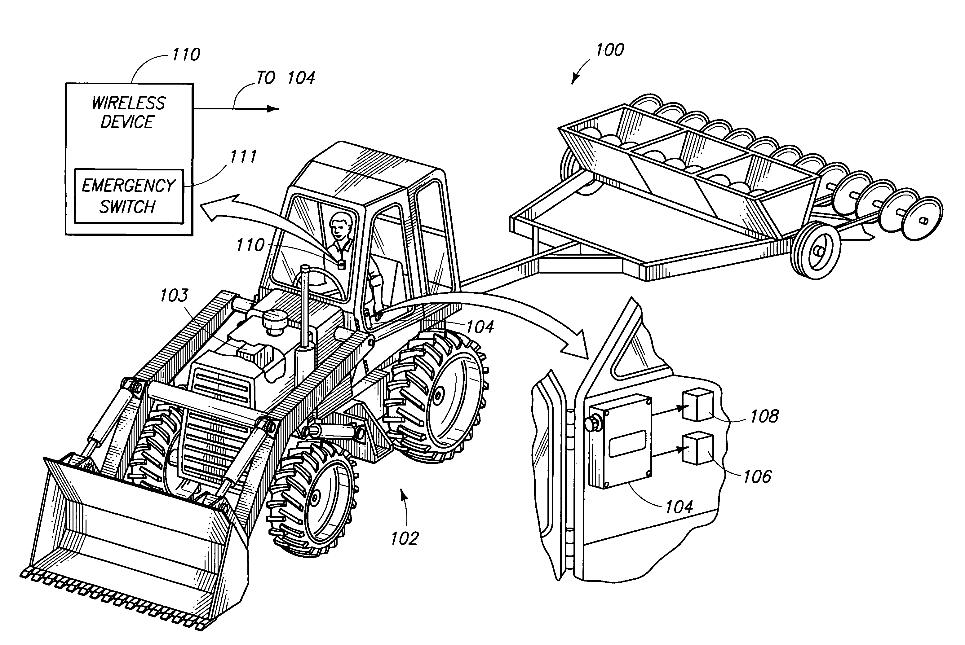
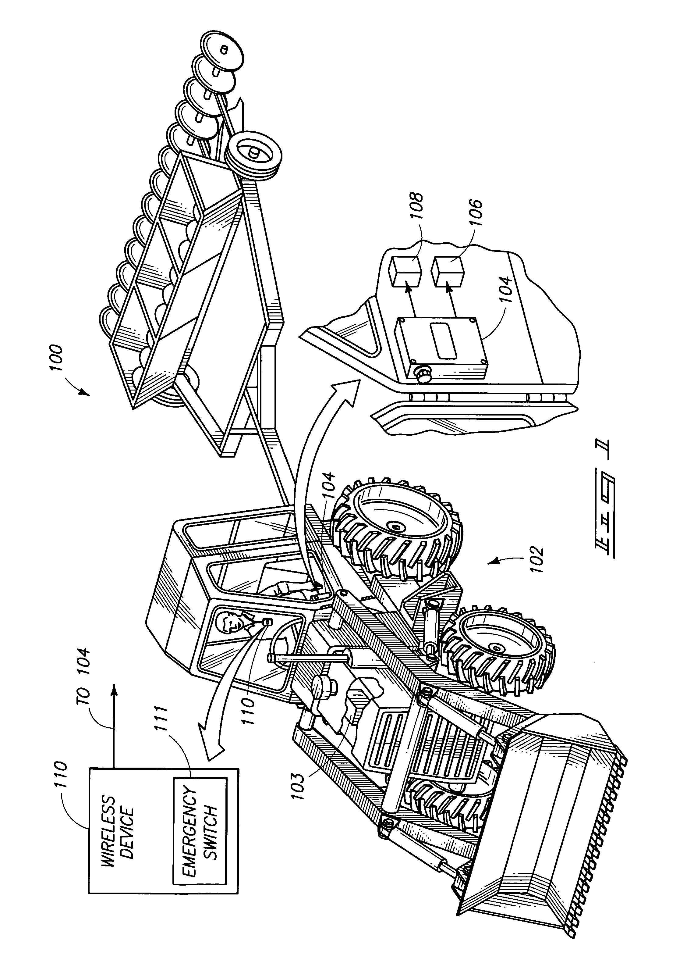
[0028]FIG. 1 is an exemplary schematic illustrating an emergency shutoff system 100 configured to control operation of a power machine 102 in accordance with various embodiments of the invention. In one example, the machine 102 may be a tractor or a similar mobile vehicle used in an agricultural environment. The power machine 102 may include an injector pump, or an ignition coil if the power machine is of the type that operates on electrical ...


PUM


Abstract

An emergency shutoff system for power machinery includes a control device housing a transmitter circuit, a receiver circuit, and a processor. A wireless device is carried by a user and configured to transmit information to the control device to cause the processor to shut down operation of the power machinery. The control device is configured to transmit a distress signal to a third party located remote from the power machinery, and provide an indication to attract attention of others. Transmission of the distress signal is initiated after receiving the control signals to shut down the power machinery. Selective operation of a single emergency switch provided on the wireless device is configured to cause the control device to operate in a plurality of different modes including disabling operation of the power machinery and preventing a third party from inadvertently initiating operation of the power machinery from a remote location.

Description

TECHNICAL FIELD[0001]The present invention pertains to a wireless system for controlling machinery. More particularly, aspects of the invention relate to a wireless user monitoring system for controlling processing machinery, locating a user and contacting emergency personnel. Methods of controlling processing machinery are also described.BACKGROUND OF THE INVENTION[0002]During the past few decades, the agricultural industry underwent many changes ranging from the increased use of technology to boost production to the slow, but constant erosion of the family farm not only in the United States, but in other countries as well. To date, agriculture remains one of the most hazardous industries in the United States and other countries. The occupational environment for this industry continues to present a wide variety of hazards to workers, including chemical exposures, noise, organic dusts, psychological stresses, and physical and mechanical exposures that may result in traumatic injury....

Claims


Application Information

Patent Timeline
Patent Type & Authority Patents(United States)
IPC IPC(8): G08B1/08H04Q7/00A01B71/08E02F9/24F16P3/00G08B25/01
CPCA01B71/08E02F9/24G08B25/005G08B25/016G08B25/001F16P3/00
Inventor LACY, TED M.BOLSTER, RANDALLLACY, BRITTON M.
Owner RED FOX & COMPANY
Why Eureka
Try Eureka