
Fuel cell and fuel cell stack

a fuel cell and stack technology, applied in the field of solid polymer electrolyte membrane type fuel cells and fuel cell stacks, can solve the problems of inclination or warpage, difficult to accurately stack these separators without sealing material deterioration, and difficulty in avoiding electrical short circuit between adjacent separators, so as to improve the corrosion resistance of separators and avoid electrical short circuits

Inactive Publication Date: 2006-03-21
HONDA MOTOR CO LTD
View PDF21 Cites 38 Cited by
  • Summary
  • Abstract
  • Description
  • Claims
  • Application Information

AI Technical Summary

Benefits of technology

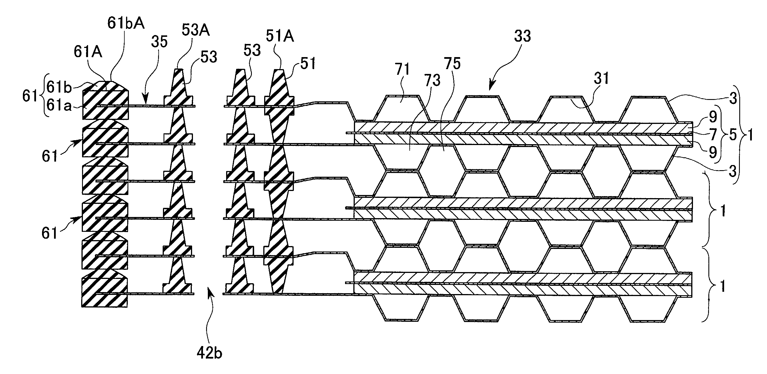
[0024]According to the first aspect of the present invention, a fuel cell comprising a pair of separators which clamp outsides of a pair of electrodes (for example, electrodes 9 in the embodiment) provided on both sides of a solid polymer electrolyte membrane (for example, the solid polymer electrolyte membrane 7 in the embodiment), wherein the fuel cell further comprises a nonconductive picture frame-shaped member (for example, picture frame-shaped members 61, 81, 91, 101, 121, 131, 141, 251 and 261 in the embodiments) which allows increasing and decreasing of a space between separators, while sealing the gap between separators, is provided at the outer edge of said separator.
[0062]According to the above construction, since both surfaces of the exposed metal surfaces at the outside portion of the reaction surface peripheral sealing member are covered by the insulating members, the corrosion resistance of separators is improved and the electrical short circuiting between adjacent separators can be avoided.

Problems solved by technology

At the time of stacking the separators, if there is a difference in thickness between the membrane electrode assembly, or if there is bending or distortion in the separator (particularly, in a thin separator made of metal), or if the compressive load applied from the opposite ends of the fuel cell stack is non-uniform, the separators are not stacked parallel with each other, and inclination or warp occurs.
Hence, the compression amount of each sealing material becomes unequal, and as a result, sealability deteriorates in sealing material having a small amount of compression.
At the time of stacking the separators, it is also difficult to stack these separators accurately without shifting their relative positions along the electrode reaction plane.
However, if the sealing material or the membrane electrode assembly shrinks in the stacking direction of the separators due to deterioration with the lapse of time, or the fuel cell expands or contracts due to the influence of heat or the like, the following problems will occur.
Hence, a gap may be caused between the separator and the sealing material or the membrane electrode assembly, thereby causing a decrease in the power generation performance, and consequently causing a situation where power generation is not possible.
A picture frame-shaped member made of resin or the like, however, since this does not expand in the stacking direction of the separators, this cannot accommodate the expansion of the space between separators.

Method used


Image

  • Fuel cell and fuel cell stack
  • Fuel cell and fuel cell stack
  • Fuel cell and fuel cell stack

Examples


first embodiment

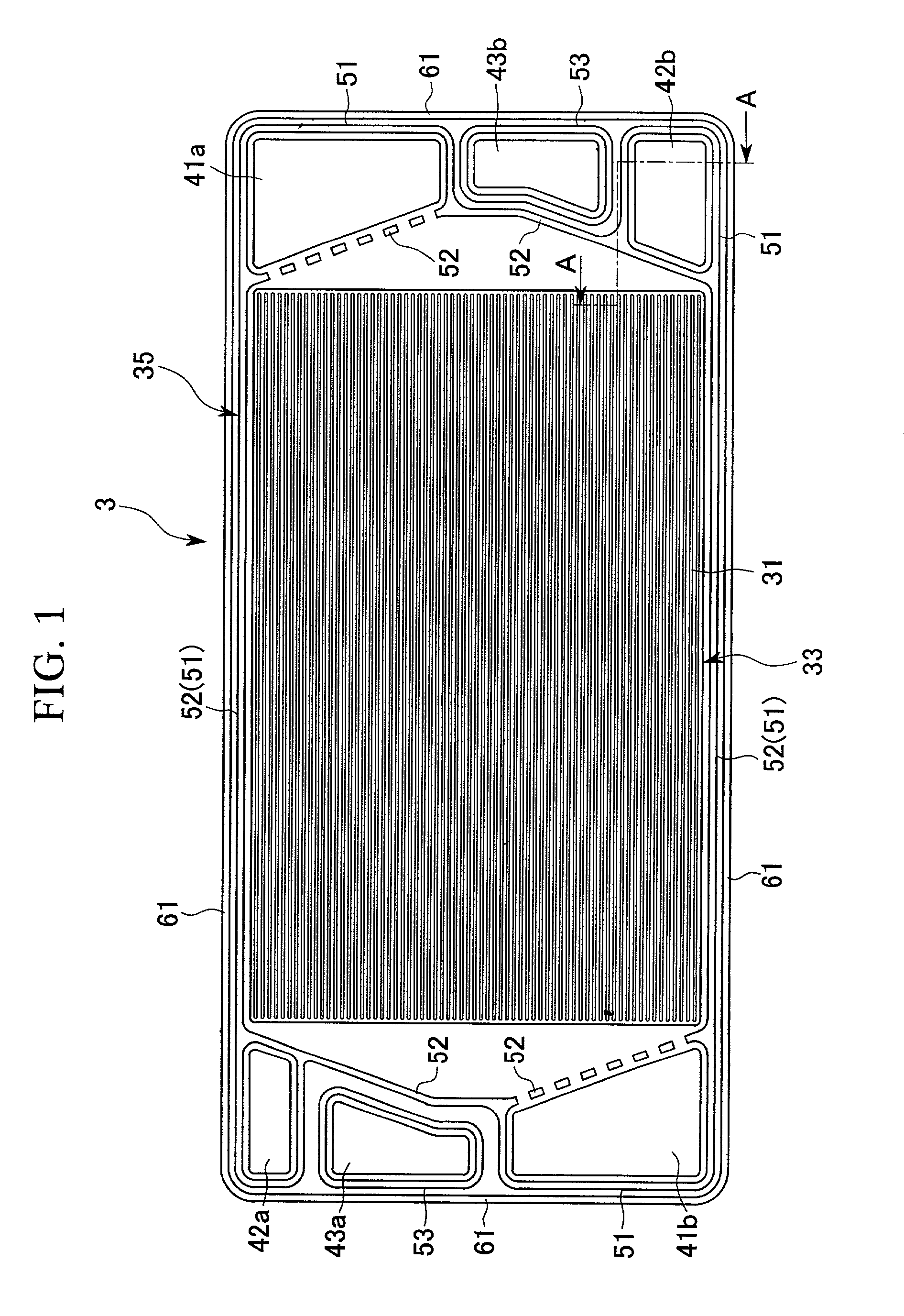
[0083]FIG. 1 is a plan view showing a separator 3 constituting a solid polymer electrolyte membrane type fuel cell 1 according to a

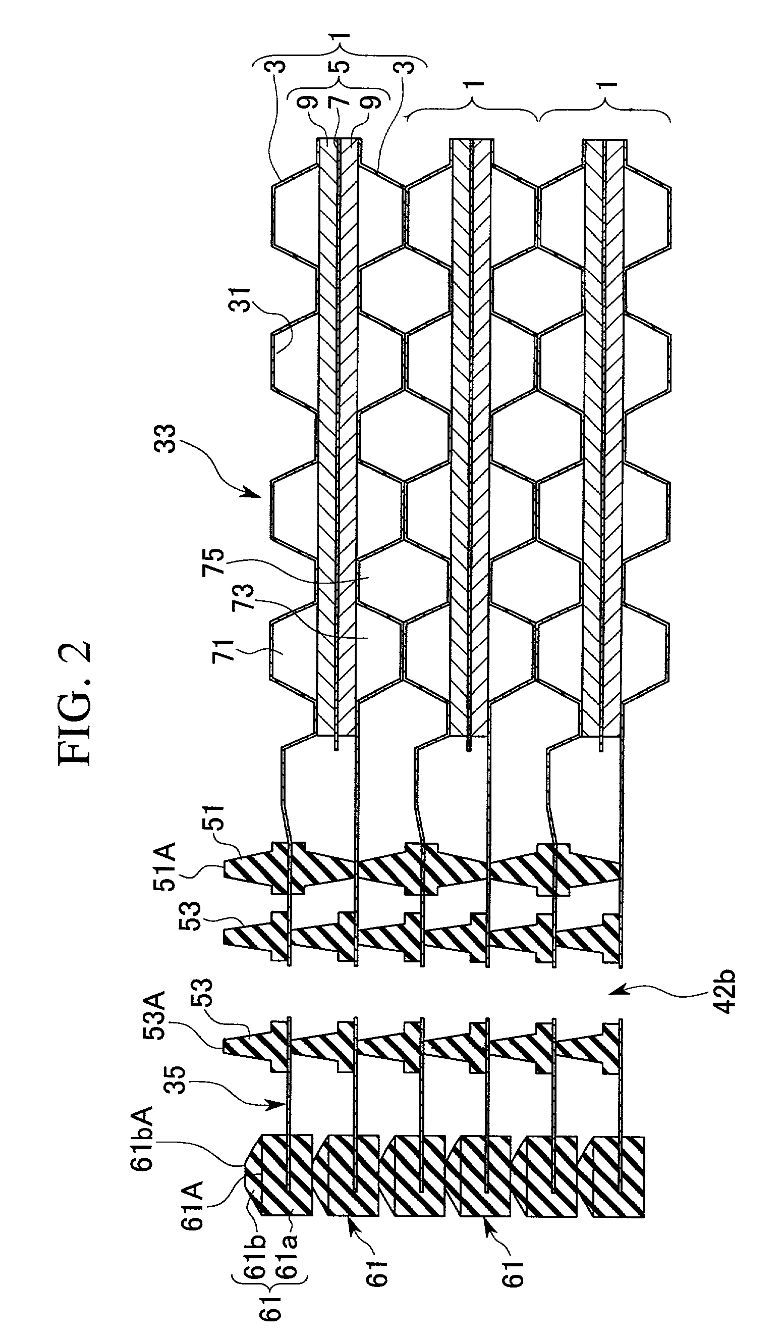
[0084]The fuel cell 1 is constructed by alternately stacking the separators 3 and an membrane electrode assembly 5 formed by sandwiching a solid polymer electrolyte membrane 7 by a pair of electrodes 9, as shown in FIG. 2, and a fuel cell stack is formed by stacking a plurality of unit fuel cells 1.

[0085]As shown in FIG. 1, the separator 3 comprises a corrugated sheet portion 33 in which a plurality of concave portions 31 having a certain height are formed at a certain pitch by press molding a stainless steel plate material having a plate thickness of from 0.2 to 0.5 mm, and a plane portion 35 for mutually contacting edge portions located outside of each corrugated sheet portion 33 through a sealing material.

[0086]This separator 3 is provided with an inlet side oxidant gas communication hole 41a for passing an oxidant gas therethrough and an inlet side f...

second embodiment

[0133]A fuel cell according to the present invention will now be described.

[0134]FIG. 5 is a cross-section showing the main parts of the fuel cell.

[0135]The same constituents as those of FIG. 1 are denoted by the same reference symbols as in FIG. 1, and description thereof is omitted.

[0136]A picture frame-shaped member 101 according to this embodiment has a different basic construction from that of the first embodiment and the modification examples thereof which use elastic deformation to absorb increase and decrease, in that increase and decrease in the stacking direction of the separators is absorbed mechanically.

[0137]This picture frame-shaped member 101 has a convex shape in section with a protruding portion 101a protruding from a base portion 101b, and the protruding portion 101a is arranged so as to face the inside of the fuel cell stack (the right side in FIG. 5) and the outside thereof (the left side in FIG. 5) alternately along the stacking direction of the separators.

[0138...

third embodiment

[0156]A fuel cell according to the present invention will now be described.

[0157]FIG. 8 is a cross-section showing the main parts of the fuel cell.

[0158]The same constituents as those of FIG. 2 are denoted by the same reference symbols as in FIG. 2, and description thereof is omitted.

[0159]A picture frame-shaped member 131 according to this embodiment has a bowl-like inclined face with an end face 131A on the cooling plane 3B side of the separator 3 and an end face 131B on the reaction plane 3A side of the separator 3 inclined with respect to the cooling plane 3B and the reaction plane 3A, with the inner side down (in the cross-section showing the main part in FIG. 8, the right side down).

[0160]In this embodiment, the separator positioning device is constituted by these end faces 131A and 131B.

[0161]According to this construction, increase and decrease of the space between separators can be absorbed by relative sliding movement of the end face 131A of one of the adjacent picture fra...


PUM

PropertyMeasurementUnit
Shapeaaaaaaaaaa
Elasticityaaaaaaaaaa

Abstract

In a solid polymer electrolyte membrane type fuel cell of the invention, where a pair of electrodes are provided on opposite sides of a solid polymer electrolyte membrane, and the outside thereof is clamped by a pair of separators, and nonconductive picture frame-shaped members 61 are arranged at the outer edge portions of the separators, for allowing increase and decrease of a space between separators, while sealing a gap between the separators.

Description

BACKGROUND OF THE INVENTION[0001]1. Field of the Invention[0002]The present invention relates to a solid polymer electrolyte membrane type fuel cell, and a fuel cell stack constituted by stacking a plurality of said fuel cell units, and more specifically relates to a technique effective in absorbing increase and decrease in the stacking direction of separators.[0003]2. Description of the Related Art[0004]Fuel cells include a solid polymer electrolyte membrane type fuel cell constituted by providing a pair of electrodes on opposite sides of the solid polymer electrolyte membrane and sandwiching the outside thereof by a pair of separators.[0005]In this fuel cell, a channel for a fuel gas (for example hydrogen) is provided on the whole surface of a separator provided facing one electrode, a channel for an oxidant gas (for example air including oxygen) is provided on the whole surface of a separator provided facing the other electrode, and a channel for a cooling medium is provided on e...

Claims


Application Information

Patent Timeline
IPC IPC(8): H01M2/08H01M2/14H01M8/02H01M8/04H01M8/10H01M8/24
CPCH01M8/0273H01M8/242H01M8/021H01M8/0254Y02E60/50H01M8/0284H01M2008/1095H01M8/0276H01M8/2483
Inventor SUENAGA, TOSHIHIKOSUGITA, NARUTOSHIOGAWA, TAKAYUKIANDOU, KEISUKEINOUE, MASAJIRO
Owner HONDA MOTOR CO LTD
Learn More