Connector

a plug-in connector and plug-in technology, applied in the direction of electrical equipment, basic electric elements, coupling device connections, etc., can solve the problems of insufficient supply, insufficient solution, essential drawbacks of surface soldering process, etc., to reduce mechanical stability of plug-in connectors, increase heat exchange area, and improve thermal conduction in the range of soldering tags

Inactive Publication Date: 2006-03-28
EPT
View PDF15 Cites 5 Cited by
  • Summary
  • Abstract
  • Description
  • Claims
  • Application Information

AI Technical Summary

Benefits of technology

[0015]These spacers may be formed by projections of the insulating material or by corresponding formation of the contact elements. Due to the formation of these spacers and the gap between two adjacent wafers, the soldering tags, the feedthrough and the solder paste received therein as so well accessible for heat transport during the surface soldering process accessible to permit the formation of a reliable soldered joint without having to do away with reproducible positioning of the plug-in connector relative to the circuit board.
[0016]Thermal conduction in the range of the soldering tags may be further improved if the insulating material is provided with recesses extending in portions along the contact elements while partly exposing the latter, so that those portions of the contact elements adjacent the soldering location may also directly be heated by convection of radiation. In this way, a maximum heat exchange area for transmission of the heat introduced from outside to the soldering location is created. The recesses are, however, selected such that mechanical fixation of the contact elements in the insulating material will be ensured at any point of time. Overall, in this embodiment operability of the soldering tags is enhanced by their increased heat exchange area, while the mechanical stability of the plug-in connector is reduced only inessentially.
[0017]Relative positioning of the plug-in connection with regard to the electrical circuit may be further improved if the wafer is designed to include a retainer member capable of being taken into engagement with a correspondingly shaped mating part on the circuit board. This retainer member may, e.g., be a snap-in or catch protrusion on the insulation part which snaps into frictional or positive engagement e.g. with a press-fit in a recess of the circuit. As an alternative, or in addition, the retainer member may also be executed through a suitable design of the soldering tags, such as by denting at least one soldering tag.
[0018]Thanks to the retainer member, the position of the plug-in connector relative to the circuit board during the soldering process is additionally stabilized, and faulty positioning which might later on result in a useless completed circuit board is avoided. This is particularly advantageous inasmuch as surface-mounting components are as a general rule pre-mounted on the circuit board by automated machines, and only then supplied to the soldering process. In this case the maximum setting force whereby such an automated machine can set a component on the circuit board or in the feedthrough, is comparatively low. The retainer members then are to be designed such that the setting force inevitably required by these will not be higher than the maximum force which the pick-and-place machines may customarily apply.
[0019]In a preferred practical example of the invention, at least one support surface as a contact surface for the adjacent wafer is formed on the lateral wall of the wafer. In this way the relative positions of the wafers among each other and maintaining the gap dimensions in accordance with the claims are ensured.

Problems solved by technology

The just-mentioned plug-in connectors do, however, exhibit essential drawbacks for the surface soldering process.
The named solutions do not, or only insufficiently, allow the supply of a sufficient amount of heat to the soldering location in the short time available for the surface soldering process.

Method used


Image

  • Connector
  • Connector
  • Connector

Examples


Embodiment Construction

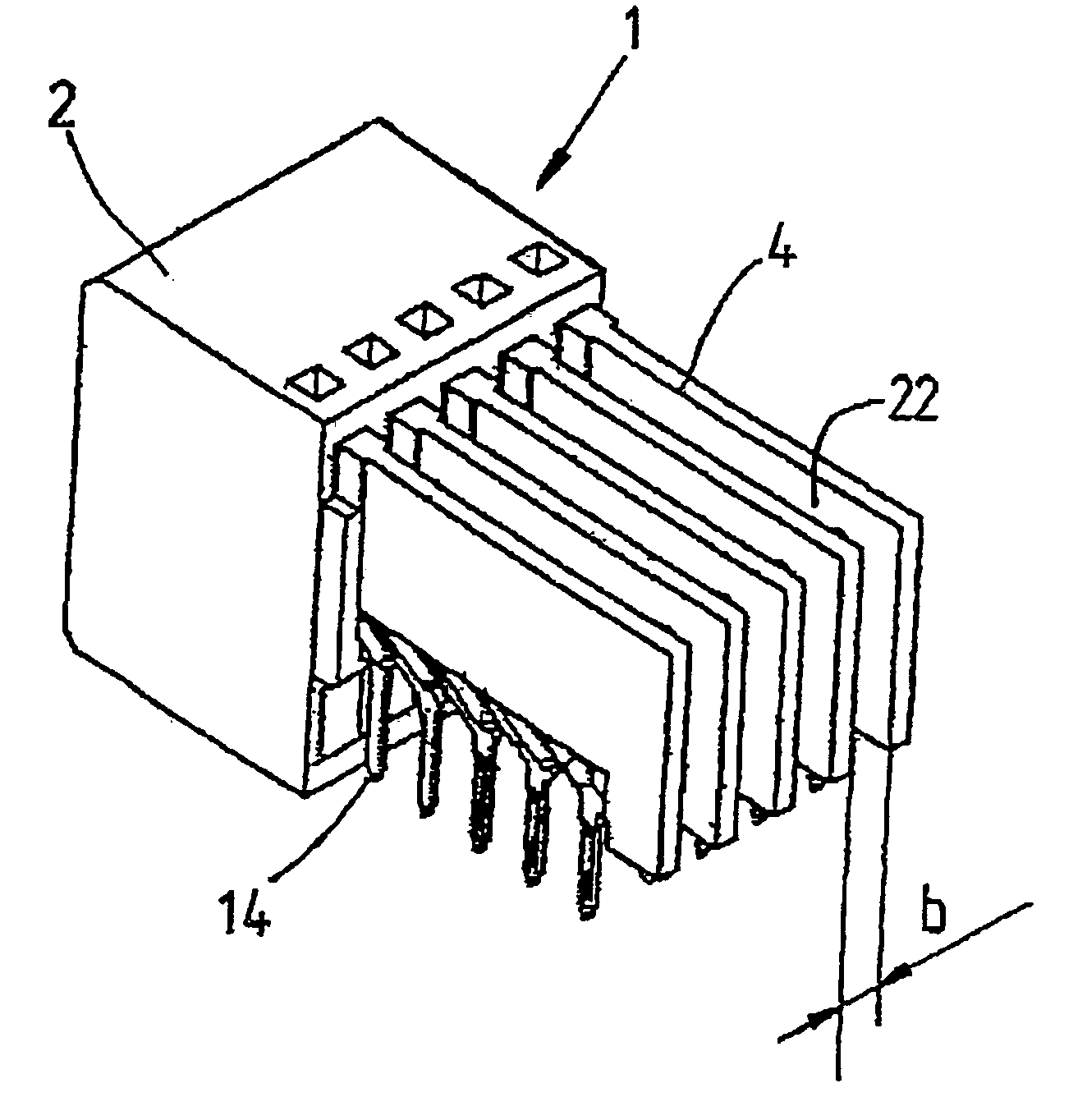
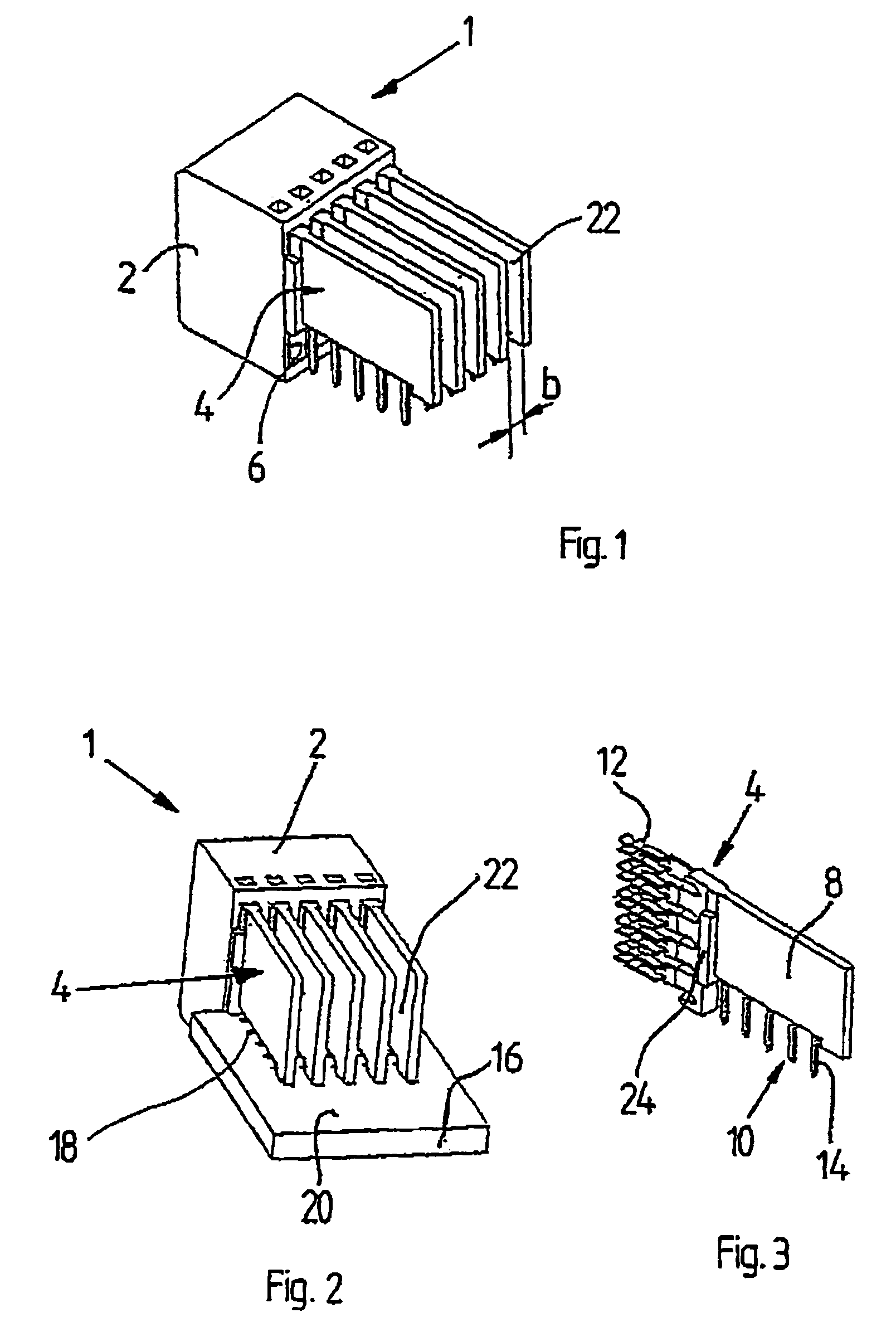
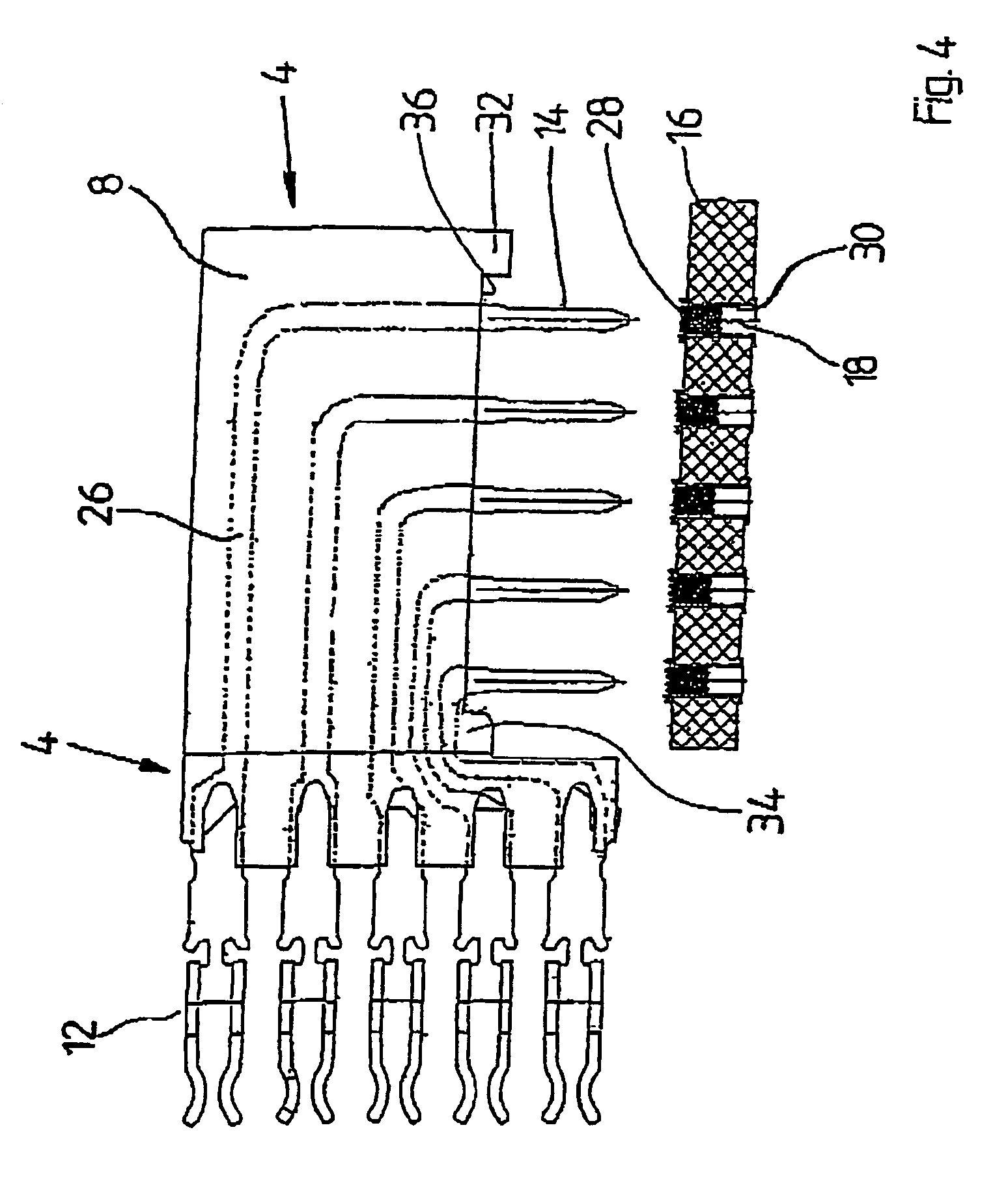
[0039]FIG. 1 shows a simplified three-dimensional representation of a plug-in connector 1 in through-hole technology. This plug-in connector 1 has a carrier part 2 in which adjacently positioned wafers 4 are arranged. The carrier part 2 has recesses 6 wherein the wafers 4 are inserted by an end portion thereof. In accordance with FIG. 3 each wafer 4 includes an insulating material 8 wherein contact elements 10 are embedded. These extend through the insulating material 8 along the plane defined thereby, wherein in the representation in accordance with FIG. 3, in the horizontal direction flexible tongue-type contact terminals 12 and in a vertical downward direction soldering tags 14 offset at right angles to each other protrude from the insulating material 8. The contact terminals 12 with the adjacent end portion of the insulating material 8 are inserted in the recesses 6 of the carrier part 2.

[0040]In accordance with FIG. 2, the plug-in connector 1 formed with a multiplicity of wafer...


PUM


Abstract

What is disclosed is a plug-in connector in through-hole technology that is suited for the surface soldering technique. The plug-in connector includes an insulating carrier part wherein a multiplicity of wafers each having soldering tags and contact terminals are inserted. In accordance with the invention, the wafers are placed at a distance from each other, whereby flow channels for supplying the heat transport medium, e.g. air, are created. In an advantageous alternative or additional development of the invention, there is formed in the range of the feedthrough a flow space permitting a flow of the heat transport medium perpendicularly to the plane of the platelets. This passage may be formed by a recess of the insulating material or by suitable spacer elements.

Description

BACKGROUND OF THE INVENTION[0001]1. Field of the Invention[0002]The invention relates to an electrical plug-in connector in accordance with the preamble of claim 1.[0003]2. Description of the Related Art[0004]Plug-in connectors generally serve for electrical connection between electrical components or electrical circuits. In electronics, circuit boards as circuit carriers have attained outstanding significance. With the aid of electrical plug-in connectors a reliable, generally releasable electrical connection between circuit carriers mostly being planar circuit boards may be established. The circuit board-side terminals of plug-in connectors are designed such that through suitable processing methods a secure electrical and mechanical connection may be produced between these plug-in connector terminals and, the circuit board. Processes to be mentioned here are the classical flow-soldering technique, the surface soldering technique (≈SMT=surface mount technology) and the press-fittin...

Claims


Application Information

Patent Timeline
Patent Type & Authority Patents(United States)
IPC IPC(8): H01R13/502H05K3/34
CPCH01R12/724H01R12/7064H01R23/688H05K3/3447
Inventor GUGLHOER, THOMAS
Owner EPT
Why Eureka
Try Eureka