Dual-beam interferometer for ultra-smooth surface topographical measurements

a topographical measurement and dual-beam technology, applied in the field of flat surface characterization, can solve the problems of limited separation distance, spurious change of optical path length in the object beam, and extreme sensitivity of conventional interferometer to environmental vibration, so as to reduce sensitivity to environmental vibration and efficiency and accuracy.

Inactive Publication Date: 2006-03-28
SEAGATE TECH LLC
View PDF19 Cites 12 Cited by
  • Summary
  • Abstract
  • Description
  • Claims
  • Application Information

AI Technical Summary

Benefits of technology

[0012]The interferometer of the present invention is a common-path interferometer. The interferometer directs two beams focused at two distinct points on the testing surface. An offset distance “d” between the two beams is provided on the target surface. In the present invention, the separation distance “d” is adjustable. The interferometer requires neither a birefringent lens nor a Wollaston prism to generate the tw...

Problems solved by technology

However, conventional interferometers are extremely sensitive to environmental vibration.
Environmental vibration can cause body movement between the interferometer and the test object, w...

Method used


Image

  • Dual-beam interferometer for ultra-smooth surface topographical measurements
  • Dual-beam interferometer for ultra-smooth surface topographical measurements
  • Dual-beam interferometer for ultra-smooth surface topographical measurements

Examples


Embodiment Construction

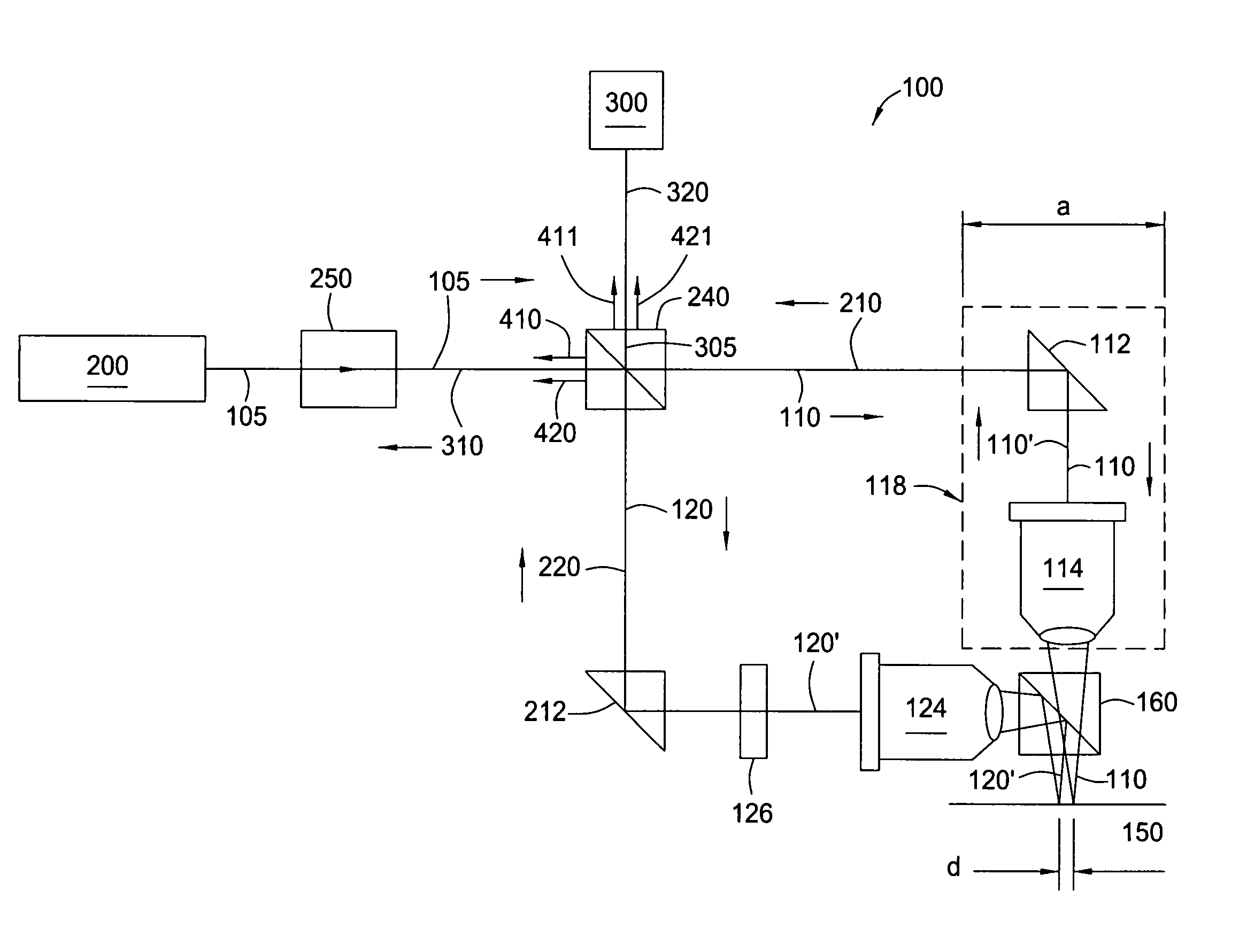
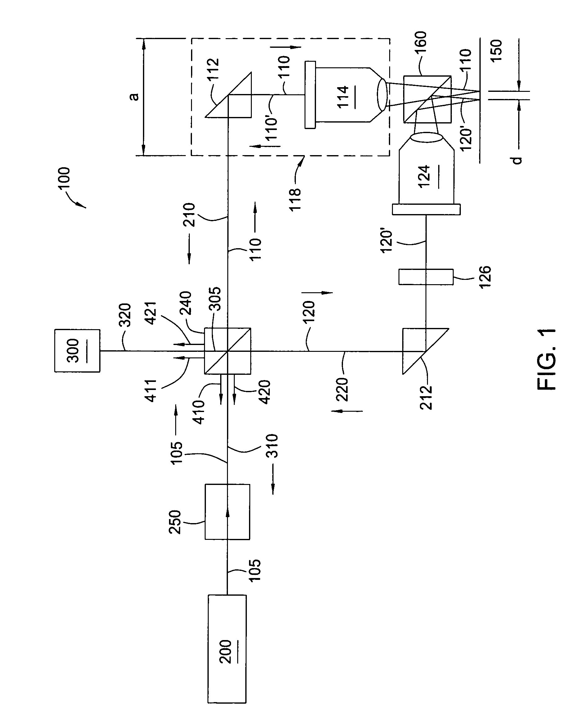
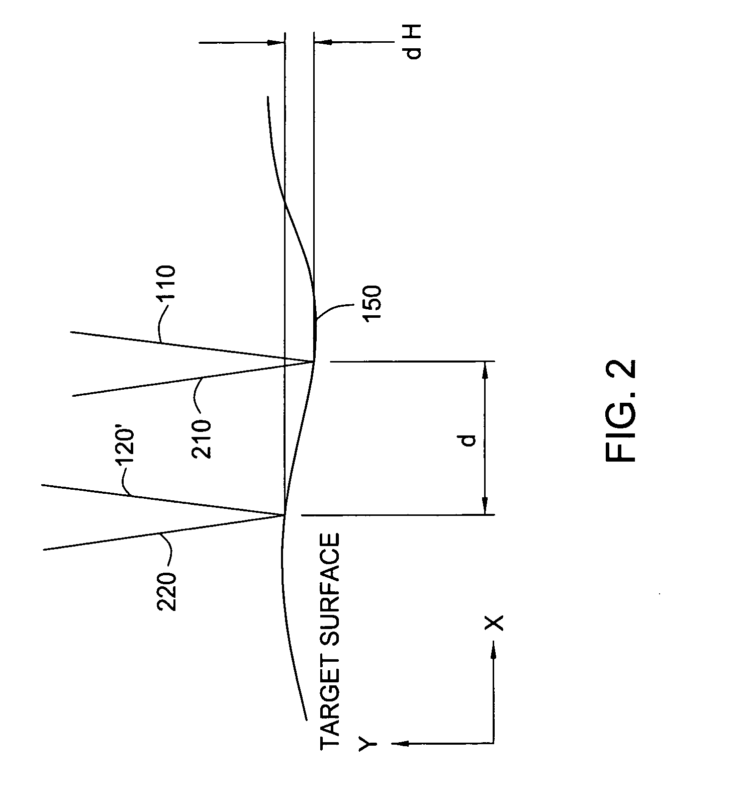
[0020]FIG. 1 presents a diagram of a dual-beam, common path optical interferometer 100 of the present invention, in one embodiment. As the title implies, two beams 110 and 120 are generated through the interferometer 100. The beams 110, 120 are directed towards a target surface 150 under analysis. In the exemplary arrangement of FIG. 1, the target surface 150 is a mirror-like, highly reflective, ultra-smooth disc surface, such as the surface of a magnetic data storage disc. However, it is understood that the present invention has utility in measuring smoothness of other smooth surfaces, such as silicon dioxide wafers.

[0021]In the present apparatus, a light source 200 is first provided. Preferably, the light source 200 defines a He—Ne laser. The laser 200 supplies a single, polarized laser beam 105, in which the beam 105 is continuous. The beam 105 may be in either the P-polarization state or the S-polarization state, depending upon the configuration of other components as will be sh...


PUM


Abstract

A method and apparatus for using a dual-beam interferometer to test surface flatness is provided. The interferometer directs two beams focused at distinct points on a testing surface, such as the surface of a magnetic recording disc. An offset distance “d” between the two beams is provided on the target surface. In the present invention, the separation distance “d” is adjustable. The feature of adjustable separation distance in the interferometer allows the interferometer to meet the different spatial frequency requirements of various applications. In operation, first and second reflected beams are returned to an intensity beam splitter, where they are split and then recombined into two new beams of substantially equal intensity. The second of the two new light beams is constructed by the interference of half intensity of the first and half intensity of second beams, and is sent to a photodiode. The photodiode generates signals in response to the changing interference fringes caused as a result of the modulation of the optical path length difference between the original first and second beams. A local height difference on the reflective surface is calculated relative to the separation distance “d”.

Description

RELATED APPLICATIONS[0001]This new application for letters patent claims priority from an earlier-filed provisional patent application entitled. That application was filed on Jun. 17, 2003 and was assigned Application No. 60 / 479,294.BACKGROUND OF THE INVENTION[0002]1. Field of the Invention[0003]The present invention relates to characterization of a flat surface. More specifically, the present invention pertains to the use of an optical interferometer to analyze the flatness of a flat surface. Further still, the present invention presents an apparatus and method for profiling a smooth surface, such as the surface of a magnetic recording disc.[0004]2. Description of the Related Art[0005]The computer industry employs magnetic discs for the purpose of storing information. In this respect, computer systems employ disc drive systems for transferring and storing large amounts of data between magnetic discs and the host computer. The magnetic discs are typically circular in shape, though o...

Claims


Application Information

Patent Timeline
IPC IPC(8): G01B9/02G01B11/30G11B5/00G11B5/012
CPCG01B11/306G11B2005/001G11B5/012
Inventor WANG, JIANMINPRESSESKY, JASON L.WANG, LI-PING
Owner SEAGATE TECH LLC
Why Eureka
Try Eureka