Method for regenerating particulate filter

a technology of particulate filter and regenerative method, which is applied in the direction of machines/engines, electrical control, separation processes, etc., can solve the problems that the temperature of the carried catalyst of the particulate filter cannot be expected to rise, the intake flow rate of the engine in a normal operation state rarely has a chance to reach a temperature level, and the accumulation of captured particulates in the particulate filter is not expected to increase. , to achieve the effect of reducing torqu

Inactive Publication Date: 2006-04-04
HINO MOTORS LTD
View PDF14 Cites 29 Cited by
  • Summary
  • Abstract
  • Description
  • Claims
  • Application Information

AI Technical Summary

Benefits of technology

[0020]Then, in a case where the engine load cannot be increased by the retarder which is off to the engine because of the clutch being off-state, the decreased intake flow rate decreases an amount of working air to the engine, leading to increased pumping loss and reduced torque. Increasing the amount of fuel injected to compensate such reduced torque raises the exhaust temperature. Moreover, an amount of exhaust gas generated through combustion in the engine decreases to lower heat capacity, which fact leads to further elevation of the exhaust temperature. Since the reduced torque due to the decreased intake flow rate is compensated, deterioration in drivability such as engine stall and / or vibration is also prevented.

Problems solved by technology

However, the exhaust gas from the engine in a normal operation state rarely has a chance to reach a temperature level at which the particulates ignite by themselves.
However, even in use of such catalytic regeneration type particulate filter, a captured amount of particulates may exceed a burned-off amount of particulates in engine operation areas with low exhaust temperature level; and continued engine operation with such low exhaust temperature level may hinder good regeneration of the particulate filter, resulting in excessive accumulation of the captured particulates in the particulate filter.
However, in a case of a vehicle continuously operated in light-load engine operation areas with extremely low exhaust temperature level at which gaseous hydrocarbons cannot be oxidized on an oxidization catalyst, e.g., in a case of a city shuttle-bus which tends to travel on congested roads, rise in temperature of the carried catalyst of the particulate filter cannot be expected even in the combination of fuel addition with arrangement of a flow-through type oxidation catalyst upstream of the particulate filter.
As a result, particulates may be extremely captured by and accumulated in the particulate filter, leading to increased exhaust pressure which adversely affects engine performance.
The particulates accumulated in a large amount may be suddenly ignited, leading to fusion damage of the particulate filter.

Method used


Image

  • Method for regenerating particulate filter
  • Method for regenerating particulate filter
  • Method for regenerating particulate filter

Examples


Embodiment Construction

[0025]An embodiment of the invention will be described with reference to the drawings.

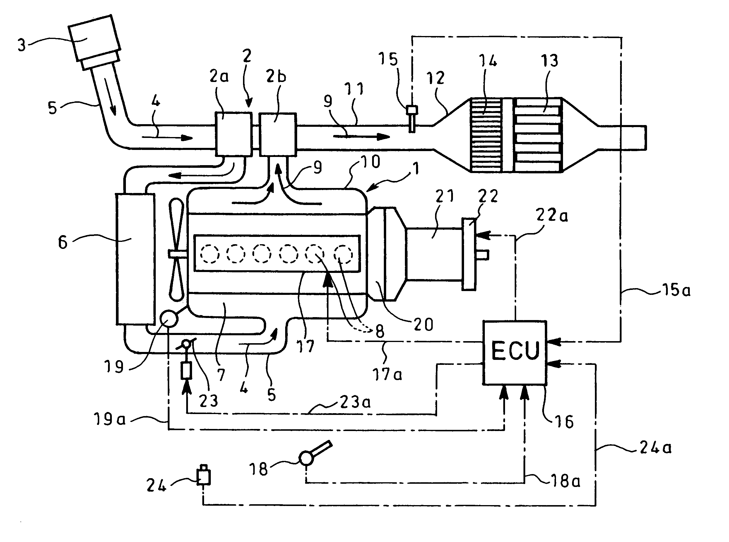
[0026]FIGS. 1 to 4 show an embodiment of the invention in which reference numeral 1 designates a diesel engine with a turbocharger 2 comprising a compressor 2a and a turbine 2b. Intake air 4 from an air cleaner 3 flows through an intake pipe 5 to the compressor 2a of the turbocharger 2 where it is pressurized. The air 4 thus pressurized is cooled by an intercooler 6 and fed to an intake manifold 7 where it is distributed to respective cylinders 8 of the diesel engine 1 (FIG. 1 shows a case of an in-line six cylinder engine).

[0027]Exhaust gas 9 from the cylinders 8 is supplied via an exhaust manifold 10 to the turbine 2b of the turbocharger 2. After driving the turbine 2b, the exhaust gas 9 is discharged outside via an exhaust pipe or passage 11.

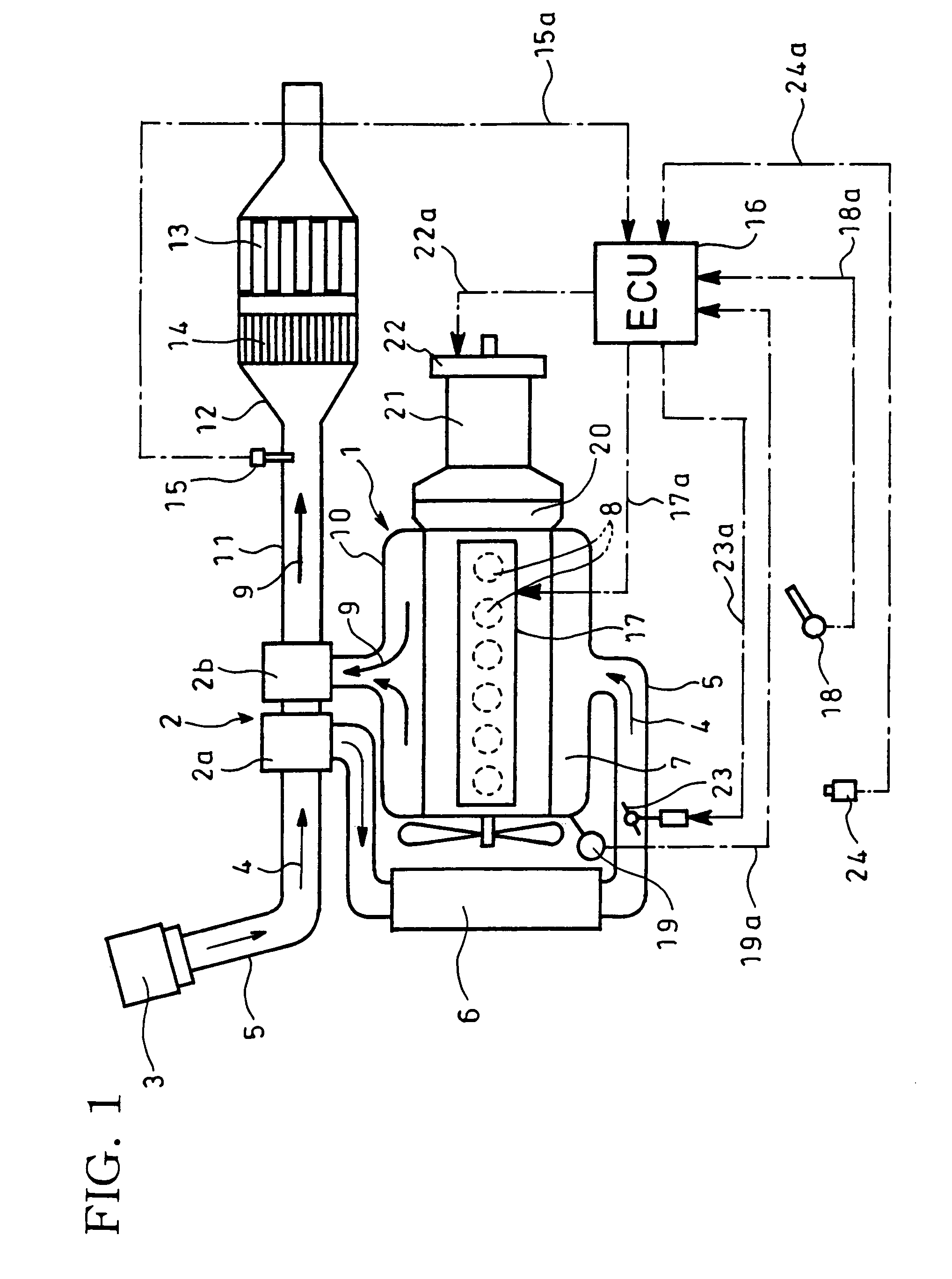
[0028]The exhaust pipe 11 has therein a filter case 12 which accommodates on its downstream side a catalytic regeneration type particulate filter 13 integra...


PUM

PropertyMeasurementUnit
crank angleaaaaaaaaaa
exhaust temperatureaaaaaaaaaa
torqueaaaaaaaaaa

Abstract

Fuel is added to exhaust gas 9 upstream of a catalytic regeneration type particulate filter 13 in an exhaust pipe 11. The fuel added is oxidized on a flow-through type oxidization catalyst 14 before the particulate filter 13 to generate exothermic heat with which captured and accumulated particulates in the particulate filter 13 are burned off to forcibly regenerate the particulate filter 13. When the driving is being performed in light-load engine operation areas upon forcible regeneration of the particulate filter 13, a retarder 22 is activated, with an accelerator pedal retaining its on-state, and an amount of fuel injected is increased to compensate reduction of torque due to such activation of the retarder 22.

Description

BACKGROUND OF THE INVENTION[0001]1. Field of the Invention[0002]The present invention relates to a method for regenerating a particulate filter.[0003]2. Description of the Related Art[0004]Particulates or particulate matter in exhaust gas from a diesel engine is mainly constituted by carbonic soot and a soluble organic fraction of high-boiling hydrocarbons and contains a trace of sulfate or misty sulfuric acid fraction. In order to reduce a discharged amount of particulates from the engine, a particulate filter is conventionally employed and arranged in an exhaust pipe through which the exhaust gas flows.[0005]The particulate filter of this kind is a porous honeycomb structure made of ceramics such as cordierite and having lattice-like compartmentalized passages; alternate ones of the passages have plugged inlets and the remaining passages with unplugged open inlets are plugged at their outlets. Thus, only the exhaust gas passing through the thin porous compartment walls is discharg...

Claims


Application Information

Patent Timeline
Patent Type & Authority Patents(United States)
IPC IPC(8): F01N3/00F02D45/00B01D46/42B01D53/86B01D53/94F01N3/02F01N3/023F01N3/025F01N3/029F01N3/035F01N3/24F01N13/02F02D41/02F02D41/04F02D41/12
CPCF01N3/023F01N3/035F02D41/0245F01N13/0097F02D41/029F02D41/12F02D2041/026Y02T10/26Y02T10/12
Inventor IGARASHI, TATSUKISHIMOKAWA, KIYOHIRO
Owner HINO MOTORS LTD
Why Eureka
Try Eureka