Chopper folder for rotary press

a rotary press and chopper technology, applied in the direction of folding thin materials, mechanical working/deformation, thin material processing, etc., can solve the problems of high manufacturing cost, large overall size of the apparatus, complex structure, etc., and achieve the effect of short transmission path, high-speed operation, and elimination of gears

Inactive Publication Date: 2006-04-04
TOKYO KIKAI SEISAKUCHI LTD
View PDF11 Cites 14 Cited by
  • Summary
  • Abstract
  • Description
  • Claims
  • Application Information

AI Technical Summary

Benefits of technology

[0041](1) The blade holder—which is connected via the link to the crank arm fixed to the output shaft of the prime mover—is supported by the guide units in order to reciprocate the chopper blade in the direction perpendicular to the conveyance plane of the signature. This configuration enables realization of a simple and compact drive transmission system which consists of a considerably small number of components, eliminates the necessity of gears, and has a very short transmission path. In addition, since vibration, resonation, and noise are hardly generated due to reciprocation of the chopper blade, silent, high-speed operation is enabled, and durability and productivity are improved.
[0042](2) The simple and compact drive transmission system is constructed by use of members of simple shape, without use of expensive members such as gear units. Therefore, the number of components can be reduced in order to reduce manufacturing cost.
[0043]Preferably, the guide unit comprises sliders provided at opposite ends of the blade holder; and two guide rails arranged along the conveyance direction and adapted to guide the sliders. The guide rails are supported such that a clearance greater than the thickness of the signature is provided between the guide rails and the conveyance plane and each guide rail has a guide surface perpendicular to the conveyance plane. Guided portions of the sliders are movable, while maintaining close contact with the guide surfaces of the guide rails at all times.
[0044]In this case, the following additional effect is achieved.
[0045](3) Since the guided portions of the sliders provided at the opposite ends of the blade holder always maintain close contact with the guide surfaces of the guide rails, the chopper blade is reciprocated, while its motion along a plane perpendicular to the reciprocating motion is restricted. Therefore, vibration, etc. are not generated at the drive transmission system or the chopper blade, so that the signature can be smoothly pushed into the space between the folding rollers. Accordingly, folding accuracy is improved, and resonation and noise can be eliminated completely.

Problems solved by technology

(1) Due to employment of two planetary gear mechanisms, the structure becomes complex, and a large number of gears, which require some backlash, must be used as structural components.
In addition, the overall size of the apparatus becomes large as a result of the large stroke of the chopper blade, and manufacturing cost is high.
However, the masses of the intermediate gears and the small gears revolving about the respective center lines break the dynamically balanced state of the rotary motion system, so that vibration, resonation, and noise are generated as a result of play such as backlash of gears, and the durability of the apparatus is impaired.
(3) The above-described vibration propagates to the chopper blade via the arms, so that the chopper blade vibrates, resulting in breakage of signatures and decreased folding accuracy.
Further, resonation, etc., caused by the vibration makes coping with increased operation speed of rotary presses difficult.
In addition, as a result of backlash of gears and variation in load acting on the crank pin portions, vibration and noise are generated, so that the chopper blade vibrates and / or resonates.
Therefore, the rigidity of the chopping blade is difficult to maintain, and therefore, the chopping blade vibrates easily.
Therefore, the chopper blade moves upward and downward, while vibrating horizontally in the longitudinal direction of the chopper blade and in the direction perpendicular thereto, so that the accuracy in folding signatures is impaired, and the apparatus cannot cope with increased operation speed of rotary presses.
(3) The linear-feed crank mechanism is mainly formed of a considerably expensive gear box which includes a large number of components.
In addition, since the crank members are rotated through mutual, direct engagement between gears provided on the rotary shafts of the crank members, backlashes of the gears are accumulated, resulting in generation of large play.
Therefore, manufacturing cost is high, and theoretical or ideal dimensions cannot be obtained, so that the apparatus causes complicated motion with vibration.
Further, excessive force is easily generated, because of dimensional errors of the respective members.
When the clearance between movable members is increased so as to dissipate such excessive force, durability is impaired.
(1) Since the reciprocal linear-motion unit for moving the chopper blade upward and downward is realized by a planetary gear box including an internal gear and a small gear, the apparatus has a complex structure and is formed of considerably expensive components.
Therefore, manufacturing cost is high.
As a consequence of these dimensional relationships, the chopper blade moves within a large stroke corresponding to the pitch circle diameter of the internal gear, resulting in an increase in the size of the apparatus.
(3) Moreover, as a consequence of the large stroke of the chopper blade, the speed of reciprocal motion of the guide portion for guiding the motion of the chopper blade along the direction of reciprocal linear motion increases, so that the bearings wear quickly, and excessive force acts on the crank pin engaged with the chopper blade, resulting in impaired durability.
(4) Further, as described above, difficulty is encountered in obtaining the theoretical or ideal dimensional relationship in relation to the gears and the crank radius through precise matching and assembly, as well as in operating and maintaining the apparatus to move the chopper blade precisely linearly.
However, since the crank pin and the elongated hole wear, durability is low.
Further, vibration and resultant resonation lower folding accuracy and make coping with high speed operation difficult.

Method used


Image

  • Chopper folder for rotary press
  • Chopper folder for rotary press
  • Chopper folder for rotary press

Examples


Embodiment Construction

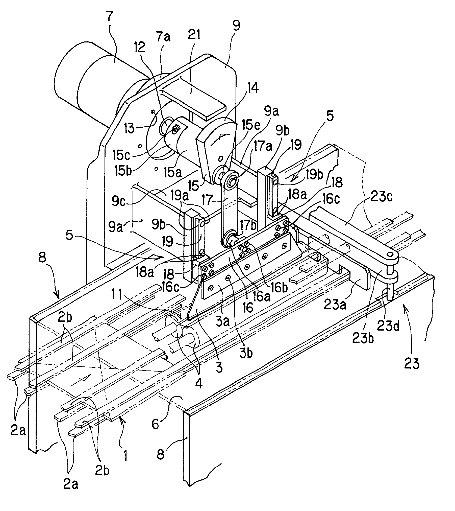
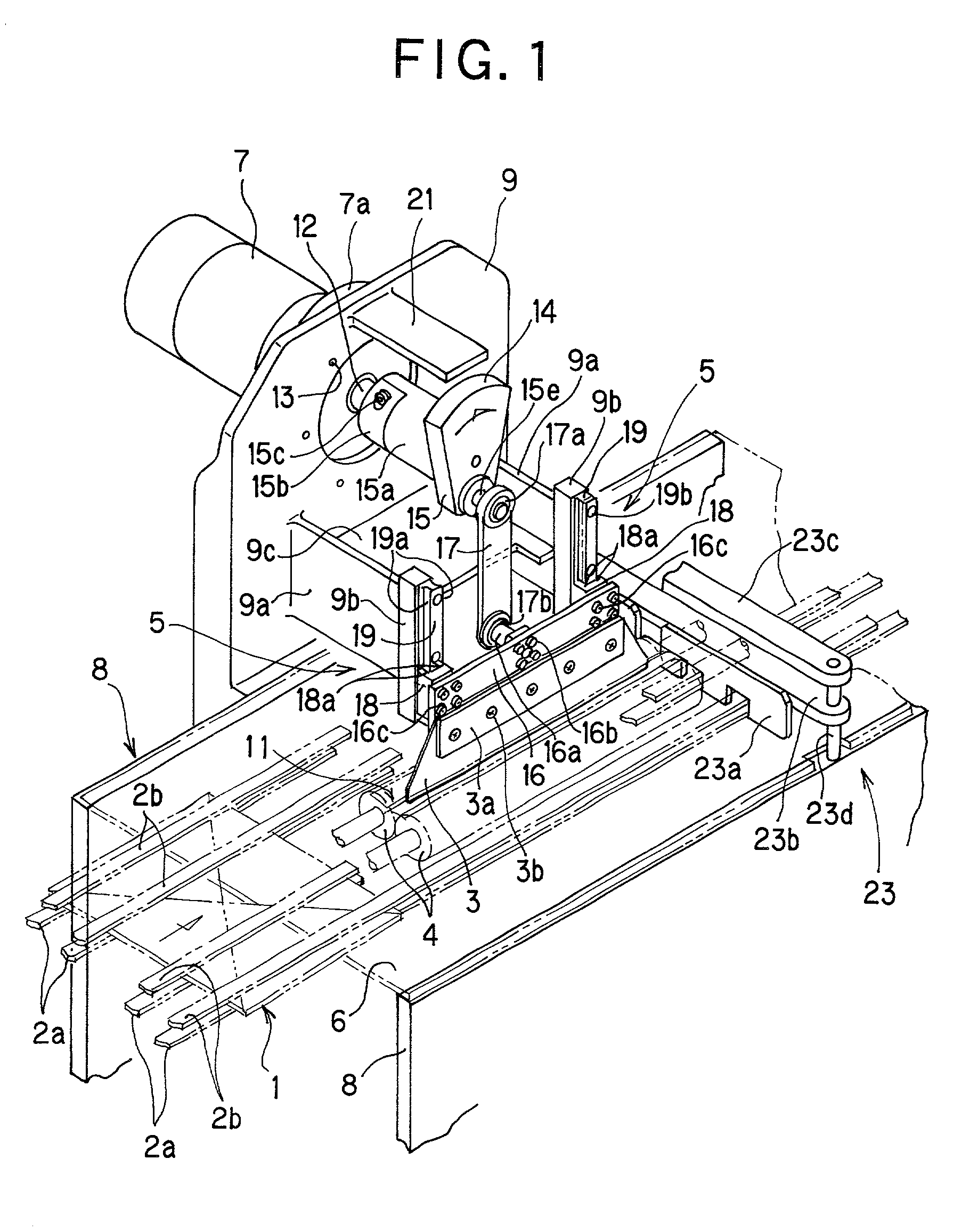
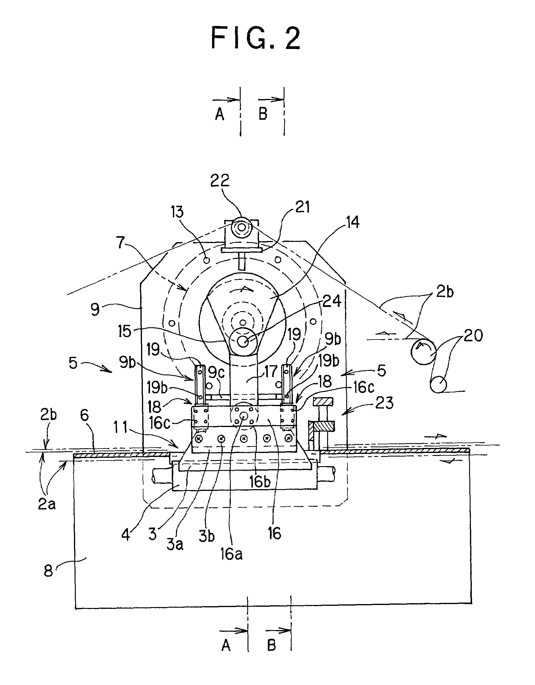
[0052]A chopper folder for a rotary press according to an embodiment of the present invention will be described with reference to the drawings.

[0053]In the chopper folder, vertical frames 8 extending in a conveyance direction of a signature 1 are disposed in parallel, with a predetermined clearance being formed therebetween, to thereby define the width of a conveyance plane along which the signature 1 is conveyed. Opposite side edges of a chopper table 6, which defines the conveyance plane, are fixed to the upper ends of the frames 8. A slit-shaped opening 11 is formed in the chopper table 6 at a central region of the chopper table 6 with respect to the conveyance direction of the signature 1. The opening 11 is located substantially at the center of the chopper table 6 with respect to the transverse direction, or the direction perpendicular to the conveyance direction, and has a length greater than the length of the signature 1 in the conveyance direction of the signature 1.

[0054]Tw...


PUM

PropertyMeasurementUnit
timeaaaaaaaaaa
thicknessaaaaaaaaaa
dynamic imbalance forcesaaaaaaaaaa

Abstract

A chopper folder for a rotary press folds signatures which are periodically conveyed, one signature at a time, from a folding machine. The chopper folder includes a pair of folding rollers for folding a signature parallel to the conveyance direction, a prime mover, a crank arm fixed to an output shaft of the prime mover to be rotated together with the output shaft, a blade holder connected to the crank arm via a link, a chopper blade held in the blade holder and adapted to push the signature from an upper surface thereof in order to insert the signature into a space between the pair of folding rollers, and guide units for restricting motion of the blade holder such that the blade holder reciprocates only in a direction perpendicular to a conveyance plane along which the signature is conveyed.

Description

BACKGROUND OF THE INVENTION[0001]1. Field of the Invention[0002]The present invention relates to a chopper folder for a rotary press for folding signatures periodically conveyed from a folding machine of a rotary press, and more specifically to a chopper folder equipped with a blade for pushing a signature into a space between a pair of folding rollers in order to fold the signature parallel to the conveyance direction.[0003]2. Description of the Related Art[0004]Conventional chopper folders have employed various schemes in order to move a chopper blade; e.g., a scheme in which a chopper blade is moved along an arcuate path and a scheme in which a chopper blade is moved along a linear path. In recent years, in order to cope with increased operation speed of rotary presses, the linear motion scheme—which can reduce the inertia of a movable portion—has been employed in many cases. Techniques in relation to such a linear motion scheme are disclosed in, for example, Japanese Patent Appl...

Claims


Application Information

Patent Timeline
Patent Type & Authority Patents(United States)
IPC IPC(8): B31F1/10B65H45/18B65H45/22
CPCB65H45/22B65H45/18
Inventor KITAI, MITSUOIIIZUMI, YUUJINANBA, TAKEO
Owner TOKYO KIKAI SEISAKUCHI LTD
Why Eureka
Try Eureka