Pressure measurement device

Inactive Publication Date: 2006-04-11
DATA SCI INT
View PDF73 Cites 182 Cited by
  • Summary
  • Abstract
  • Description
  • Claims
  • Application Information

AI Technical Summary

Benefits of technology

[0016]The pressure measurement device according to the present invention can be employed to accurately measure low pressure where head pressure artifact can constitute a significant percentage of the pressure being measured. These pressures include: venous pressure; pulmonary pressure; intracranial pressure; bladder pressure; and other pressures. The pressure measurement device measures these pressures without significant head pressure artifact and with a sufficient dynamic response.
[0017]The transducer is preferably pre-temperature compensated and disposable. In this way, the transducer, which is external to the housing, can be easily replaced without replacing the entire pressure measurement device. In many applications of the pressure measurement device, the housing is implantable remote from the area having the physiological pressure.
[0018]In one form of the invention, the pressure transmitting catheter includes a lumen filled with the pressure transmitting medium. An inner layer material surrounds the lumen and an outer layer material surrounds the inner layer material. The outer layer material is of a different hardness than the inner layer material. In a preferred embodiment, the inner layer material is harder then the outer laye

Problems solved by technology

Arterial blood pressure fluctuations, however, often make it necessary to obtain chronic, frequent measurements to identify the effect of the injected pharmaceutical agent or chemical, or to properly control an implantable medical device.
Hydrocephalitis and head injuries can cause excessive pressure buildup within the brain, resulting in death or serious brain damage.
'191 patent, the housing cannot be implanted within close proximity to the area where pressure is to be measured due to physical limitations and practical considerations of surgical procedures.
When the housing is not within close proximity to the area where pressure is to be measured, the length of the catheter that is required may be too long to assure that errors, resulting from dec

Method used


Image

  • Pressure measurement device
  • Pressure measurement device
  • Pressure measurement device

Examples


Example

[0029]In the following detailed description of the preferred embodiments, reference is made to the accompanying drawings which form a part hereof, and in which is shown by way of illustration specific embodiments in which the invention may be practiced. It is to be understood that other embodiments may be utilized and structural or logical changes may be made without departing from the scope of the present invention. The following detailed description, therefore, is not to be taken in a limiting sense, and the scope of the present invention is defined by the appended claims.

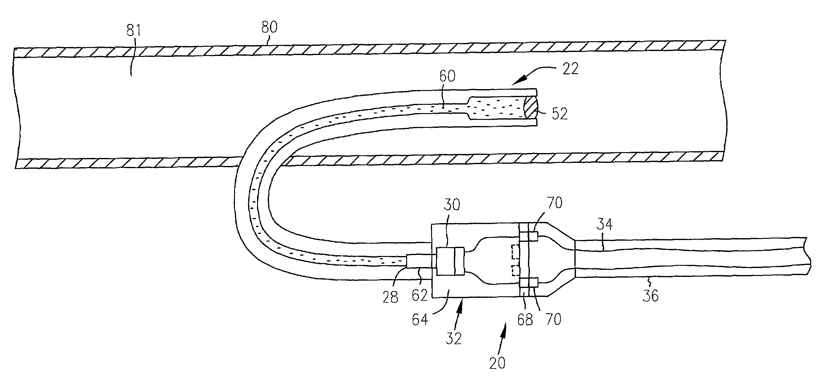
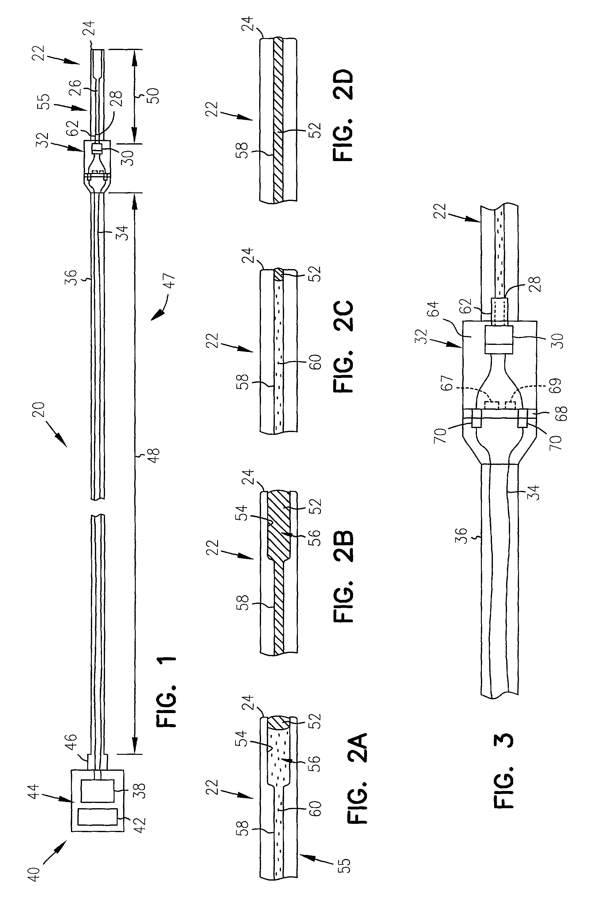
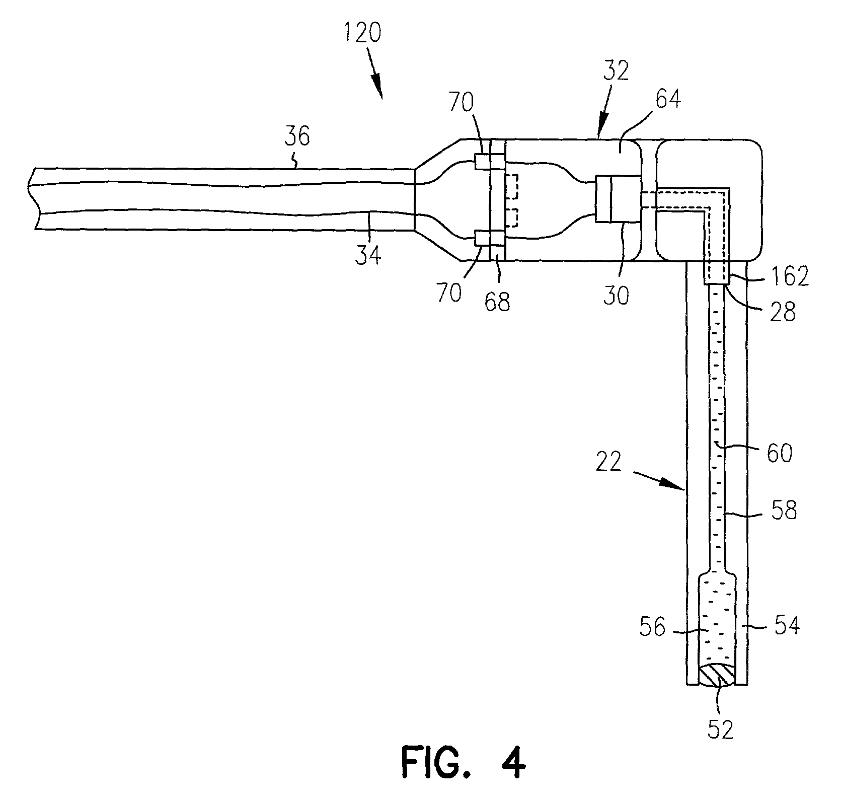
[0030]A pressure measurement device according to the present invention is illustrated generally at 20 in FIG. 1. Pressure measurement device 20 is a miniature implantable device capable of measuring internal physiological body pressure in humans or animals. The fundamental principles by which pressure measurement device 20 measures pressure are described in detail in the Brockway et al. '191 patent, which was inc...


PUM


Abstract

A device measures pressures in animals and humans and includes a pressure transmission catheter (PTC) filled with a pressure transmitting medium and implantable in an area in having a physiological pressure. A transducer communicates with the pressure transmitting medium to provide a pressure signal representing variations in the physiologic pressure on electrical wires. A connecting catheter carries the electrical wires to signal processing and telemetry circuitry, which transmits a telemetry signal representing the pressure signal to a receiver external to the animal or human. A housing holds the signal processing and telemetry circuitry, but the transducer is remote from the housing. The device is particularly useful in measuring venous pressure, pulmonary pressure, bladder pressure, or intracranial pressure without significant head pressure artifact and with a sufficient dynamic response. One embodiment of the PTC includes a multi-durometer stem.

Description

CROSS-REFERENCE TO RELATED APPLICATIONS[0001]This application is a continuation of U.S. application Ser. No. 09 / 491,233, filed Jan. 25, 2000, now U.S. Pat. No. 6,379,308 which is a divisional U.S. application Ser. No. 08 / 950,315 of U.S. Pat. No. 6,033,366, filed Oct. 14, 1997, the specifications of which are incorporated herein by reference.STATEMENT REGARDING FEDERALLY SPONSORED RESEARCH OR DEVELOPMENT[0002]Portions of this invention were developed under Contract No. 2 R44 HL55823-02, awarded by the National Institutes of Health. Therefore, the U.S. Government may have a paid-up license in portions of this invention and the right, in limited circumstances, to require the patent owner to license others on reasonable terms as provided for by the terms of the contract.THE FIELD OF THE INVENTION[0003]The present invention relates generally to implantable devices, and in particular to implantable devices for measuring various physiological pressures in humans or animals, such as blood p...

Claims


Application Information

Patent Timeline
IPC IPC(8): A61B5/00A61B5/0215A61B5/03
CPCA61B5/0215A61B5/031A61M2025/0003
Inventor BROCKWAY, BRIAN P.MILLS, PERRY ALTONMOENCH, MEL MURRAY
Owner DATA SCI INT
Why Eureka
Try Eureka