
Data acquisition method and apparatus for MR imaging

Inactive Publication Date: 2006-04-11
BOARD OF RGT THE UNIV OF TEXAS SYST
View PDF8 Cites 22 Cited by
  • Summary
  • Abstract
  • Description
  • Claims
  • Application Information

AI Technical Summary

Problems solved by technology

However, a prominently distinguishing feature of FSE images is an anomalously bright signal resulting from fat content in the tissue being imaged.
Inhomogeneity in the main magnetic field is particularly a problem at locations off the isocenter of the field system.
Finally, patient anatomy also tends to perturb the fields, rendering the technique particularly problematic.
Because of its underlying principles, the technique typically is dependent on the T1 of the water signal, and generally results in relatively low signal-to-noise ratios due to the partial recovery of the water signal during the recovery of the fat signal.
While these techniques allow for more uniform water and fat separation in the presence of field inhomogeneity, one clear drawback is the requirement for multiple data acquisitions and therefore longer scan times.
As a result, inter-echo spacing was increased, leading to substantial loss in the slice coverage for a given sequence repetition time, largely offsetting the gain of using FSE for reducing the scan time.
As in the case of FSE based Dixon technique, such shifting may lead to the disadvantage of longer acquisition times because of the increased deadtime during a sequence.
Consequently, the loss of slice coverage for a given span time, or increased scan time for a given number of slices, and an increase in blurring and greater sensitivity to flow and motion artifacts, can all result.

Method used


Image

  • Data acquisition method and apparatus for MR imaging
  • Data acquisition method and apparatus for MR imaging
  • Data acquisition method and apparatus for MR imaging

Examples


Embodiment Construction

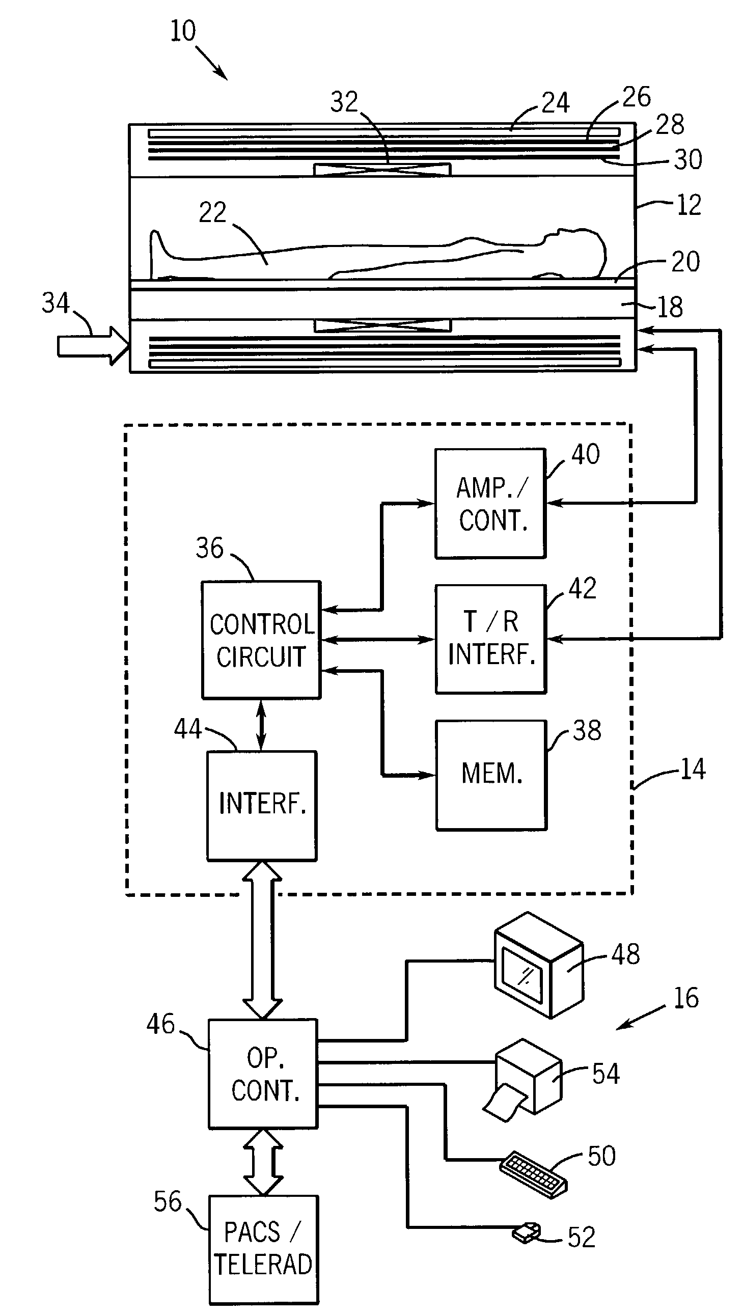
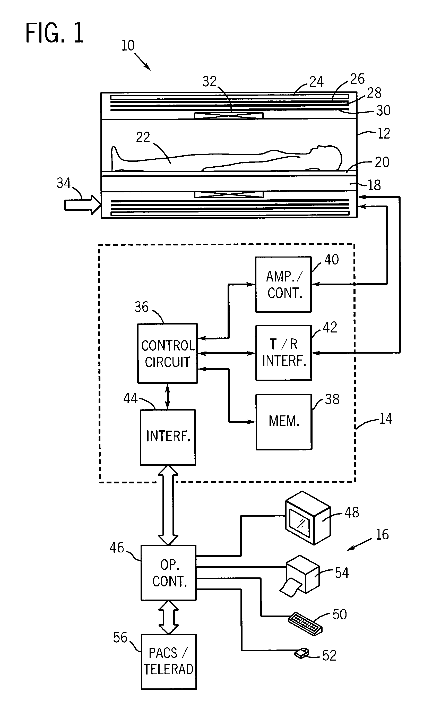
[0022]Turning now to the drawings, and referring first to FIG. 1, a magnetic resonance imaging (MRI) system 10 is illustrated diagrammatically as including a scanner 12, scanner control circuitry 14, and system control circuitry 16. While MRI system 10 may include any suitable MRI scanner or detector, in the illustrated embodiment the system includes a full body scanner comprising a patient bore 18 into which a table 20 may be positioned to place a patient 22 in a desired position for scanning. Scanner 12 may be of any suitable type of rating, including scanners varying from 0.5 Tesla ratings to 1.5 Tesla ratings and beyond.

[0023]Scanner 12 includes a series of associated coils for producing controlled magnetic fields, for generating radiofrequency rf excitation pulses, and for detecting emissions from gyromagnetic material within the patient in response to such pulses. In the diagrammatical view of FIG. 1, a primary magnet coil 24 is provided for generating a primary magnetic field...


PUM


Abstract

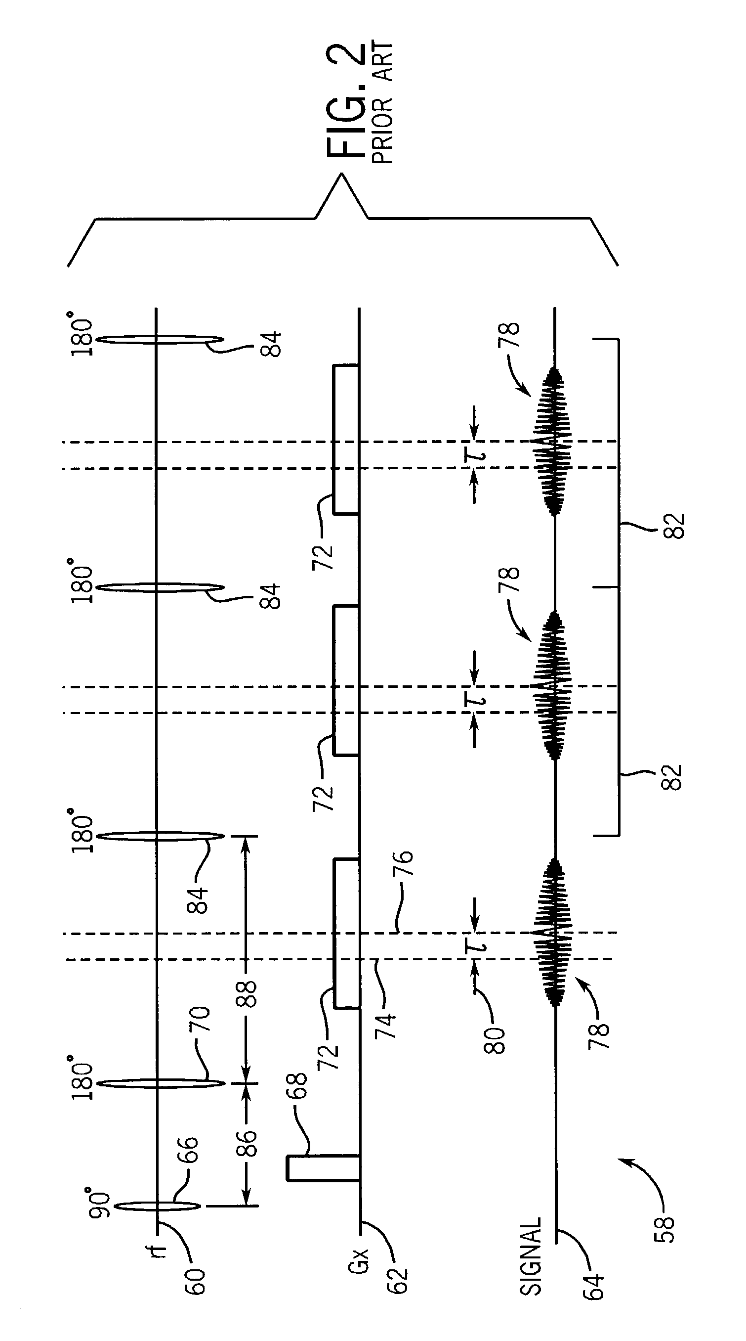
An improved technique is described for acquiring MR image data such as needed for FSE-based Dixon imaging techniques. A gradient-induced echo shift is produced in the pulse sequences by a small gradient applied along the readout axis prior to a readout pulse. When necessary, another small pulse is applied along the readout axis, equal in area and opposite in polarity to the first, to compensate for the shifting effect. Similar pulses are applied for each acquisition window. While data with non-zero phase shifts between water and fat signals are collected as fractional echoes, no increase in echo spacing is necessary with the modified acquisition strategy. Images corresponding to different phase shifts are reconstructed using phase-sensitive partial Fourier reconstruction algorithms whenever necessary. These images are then used to separate different chemical species (such as water and fat) in the object to be imaged. Increased time efficiency is therefore achieved with the improved technique, with a significant reduction in degradation due to losses in slice coverage and increased image blurring and sensitivity to flow and motion due to T2-modulation along the echo train in conventional techniques.

Description

BACKGROUND OF THE INVENTION[0001]The present invention relates generally to the field of magnetic resonance imaging. More particularly, the invention relates to a technique for providing magnetic resonance echo shifting without the need for shifting the radio-frequency pulse, or the data acquisition window, or both, such as for producing water-only or fat-only images, in a highly time efficient manner through a Dixon imaging pulse sequence.[0002]Magnetic resonance imaging (MRI) systems have become ubiquitous in the field of medical diagnostics. Over the two past decades, improved techniques for MRI examinations have been developed that now permit very high-quality images to be produced in a relatively short time. As a result, diagnostic images with varying degrees of resolution are available to the radiologist that can be adapted to particular diagnostic applications.[0003]In general, MRI examinations are based on the interactions among a primary magnetic field, a radiofrequency (rf...

Claims


Application Information

Patent Timeline
IPC IPC(8): A61B5/00G01R33/54
CPCG01R33/4828Y10S128/922Y10S128/92Y10S707/99943
Inventor MA, JINGFEI
Owner BOARD OF RGT THE UNIV OF TEXAS SYST
Learn More