
Deep resistivity transient method for MWD applications using asymptotic filtering

a resistivity transient and asymptotic filtering technology, applied in the field of measuring transient signals, can solve the problems of reducing the sensitivity of the measured em field, introducing a metal drill pipe close, and limiting the group of tools, so as to reduce the effect of the metal pip

Active Publication Date: 2006-04-11
BAKER HUGHES INC
View PDF22 Cites 28 Cited by
  • Summary
  • Abstract
  • Description
  • Claims
  • Application Information

AI Technical Summary

Benefits of technology

The present invention is a method for obtaining a parameter of interest of an earth formation using a tool with finite, non-zero conductivity. The method produces a signal from the formation that is independent of the conductivity of the tool. The signal is produced using a transmitter on the tool and received by a receiver that is axially separated from the transmitter. The received signal is dependent on the conductivity of the tool. The method also applies a filtering operation to the received signal, which eliminates the main term of the pipe contribution to the signal. The technical effect of the invention is to provide a more accurate measurement of the parameter of interest of the earth formation.

Problems solved by technology

This group of tools is naturally limited by, among other things, their applicability to only high resistivity formations and the power available down-hole.
The major problem associated with the MWD environment is the introduction of a metal drill pipe close to the area being measured.
This pipe produces a very strong response and significantly reduces the sensitivity of the measured EM field to the effects of formation resistivities and remote boundaries.
The sensitivity of such a tool to remote boundaries is low.

Method used


Image

  • Deep resistivity transient method for MWD applications using asymptotic filtering
  • Deep resistivity transient method for MWD applications using asymptotic filtering
  • Deep resistivity transient method for MWD applications using asymptotic filtering

Examples


Embodiment Construction

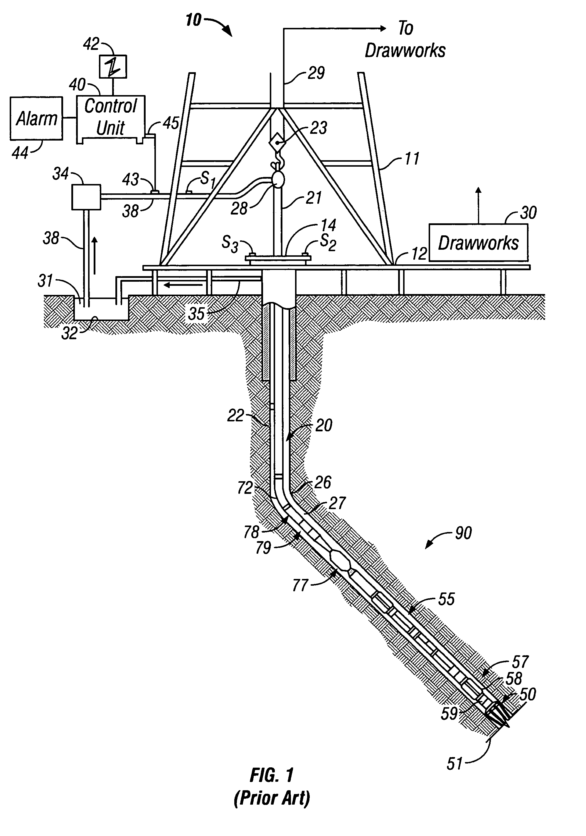
[0029]FIG. 1 shows a schematic diagram of a drilling system 10 with a drillstring 20 carrying a drilling assembly 90 (also referred to as the bottom hole assembly, or “BHA”) conveyed in a “wellbore” or “borehole”26 for drilling the wellbore. The drilling system 10 includes a conventional derrick 11 erected on a floor 12 which supports a rotary table 14 that is rotated by a prime mover such as an electric motor (not shown) at a desired rotational speed. The drillstring 20 includes a tubing such as a drill pipe 22 or a coiled-tubing extending downward from the surface into the borehole 26. The drillstring 20 is pushed into the wellbore 26 when a drill pipe 22 is used as the tubing. For coiled-tubing applications, a tubing injector, such as an injector (not shown), however, is used to move the tubing from a source thereof, such as a reel (not shown), to the wellbore 26. The drill bit 50 attached to the end of the drillstring breaks up the geological formations when it is rotated to dri...


PUM


Abstract

A method is discussed of obtaining a parameter of interest of an earth formation, typically a formation resistivity or a distance to a bed boundary, in conditions where an induction tool is using having a body with finite, non-zero conductivity. The method substantially removes the effects of the conductivity of the tool from the signal received from the earth formation. A Taylor series expansion in one half of odd integer powers of time is used to represent the received signal. At least one leading term of the Taylor series expansion can be subtracted from the second signal. A filtering operation is applied to the second signal to remove the terms most dominated by pipe effects. Typical filtering operations can be a differential filtering operation or an integral filtering operation.

Description

BACKGROUND OF THE INVENTION[0001]1. Field of the Invention[0002]The invention is related to the field of electromagnetic induction well logging for determining the resistivity of earth formations penetrated by a wellbore. More specifically, the invention relates to measuring the transient signals in an induction tool having a metallic pipe with finite, non-zero and high conductivity.[0003]2. Description of the Related Art[0004]Electromagnetic induction resistivity instruments can be used to determine the electrical conductivity of earth formations surrounding a wellbore. An electromagnetic induction well logging instrument is described, for example, in U.S. Pat. No. 5,452,761 issued to Beard et al. The instrument described in the Beard '761 patent includes a transmitter coil and a plurality of receiver coils positioned at axially spaced apart locations along the instrument housing. An alternating current is passed through the transmitter coil. Voltages which are induced in the recei...

Claims


Application Information

Patent Timeline
Patent Type & Authority Patents(United States)
IPC IPC(8): G01V1/40E21B47/00G01V3/28G01V3/30G01V3/38G06F19/00
CPCG01V3/28
Inventor BESPALOV, ALEXANDERRABINOVICH, MICHAELTABAROVSKY, LEONTY A.
Owner BAKER HUGHES INC
Learn More