
Voice-responsive command and control system and methodology for use in a signal measurement system

a command and control system and voice technology, applied in the field of voice-responsive command and control system for voice-controlled signal measurement system, can solve the problems of difficult and often impossible to probe such small components, the probe cannot be clipped to the component lead, and so as to reduce the risk of component damage and the effect of probing errors

Inactive Publication Date: 2006-04-11
AGILENT TECH INC
View PDF13 Cites 21 Cited by
  • Summary
  • Abstract
  • Description
  • Claims
  • Application Information

AI Technical Summary

Benefits of technology

[0021]Various embodiments of the present invention provide certain advantages and overcome certain drawbacks of the above and other conventional techniques. Not all embodiments of the present invention share the same advantages and those that do may not share them under the same or similar circumstances. This being the, the present invention provides numerous advantages, including those identified herein below.
[0023]Further, use of the present invention relaxes the physical constraints of having to be positioned directly in front of the oscilloscope display, which can be difficult in a crowded bench environment.

Problems solved by technology

This historic problem has become more pronounced since the introduction of surface-mount technology (SMT).
It is at times difficult and often impossible to probe such small components in such a high density interconnect environment using today's oscilloscopes.
In most cases, probes can no longer be clipped to a component lead and left unattended while the operator operates the oscilloscope.
If this difficult task can be accomplished at all, the requisite diligence required to properly probe the DUT distracts significantly the operator's concentration on the oscilloscope and captured waveform data.
Further, the inevitable intermittent contact between the probe and the component lead causing numerous probing errors.
In addition, the probe often slips off of the lead during testing, coming into contact with multiple components or component leads, inadvertently and unknowingly shorting together two or more adjacent leads, damaging the system component being tested.
This has been a long-standing problem for oscilloscope operators, although it has become more pronounced in recent decades with the advent of SMT.
The labor costs associated with performing such measurements increased accordingly.
However, this approach is time consuming, exposes components to potential damage and often results in inaccurate measurements.
In particular, when measuring high frequency signals, the addition of even the smallest solder and lead add a capacitance and / or inductance to the measured circuit, preventing accurate measurements.
However, at most such a makeshift approach are quite limited in operation, performing fixed measurement sequences characteristic of manufacturing environments.
Such devices are ineffective in testing environments more commonly occurring in component and system design testing.

Method used


Image

  • Voice-responsive command and control system and methodology for use in a signal measurement system
  • Voice-responsive command and control system and methodology for use in a signal measurement system
  • Voice-responsive command and control system and methodology for use in a signal measurement system

Examples


Embodiment Construction

I. System Environment

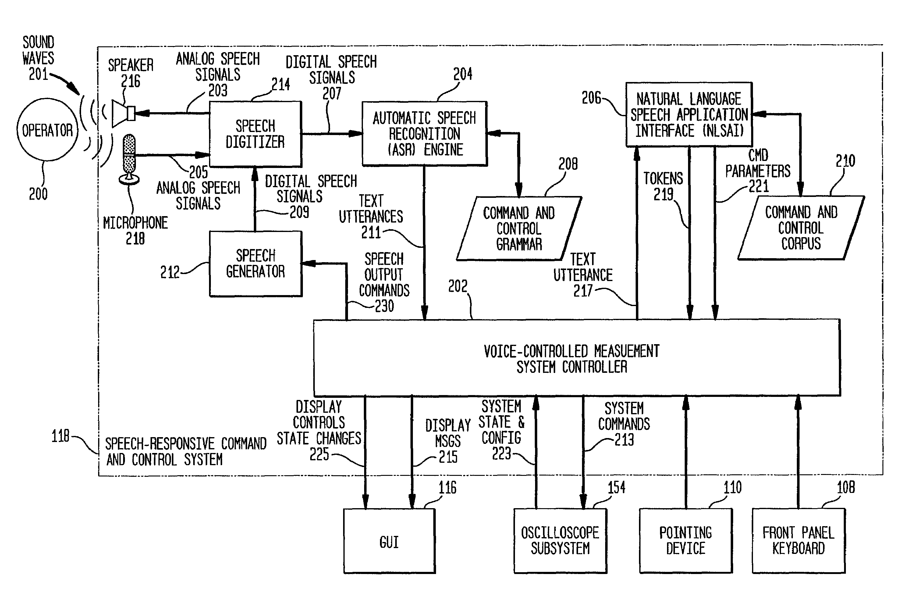
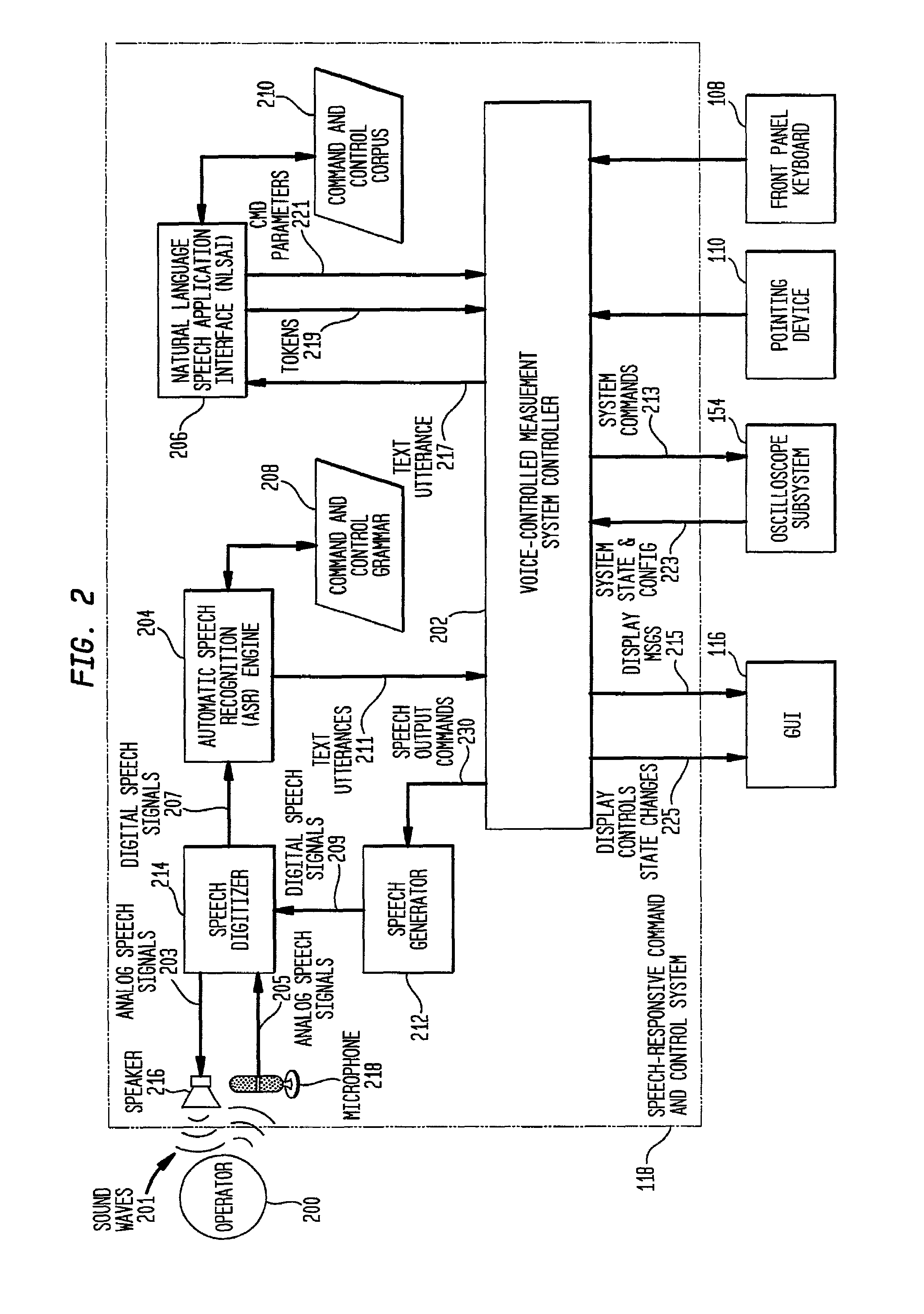
[0063]The present invention is a speech-responsive command and control system and methodology for use in a signal measurement system, enabling an operator to control certain features and functions of the oscilloscope without using manual or graphical controls.

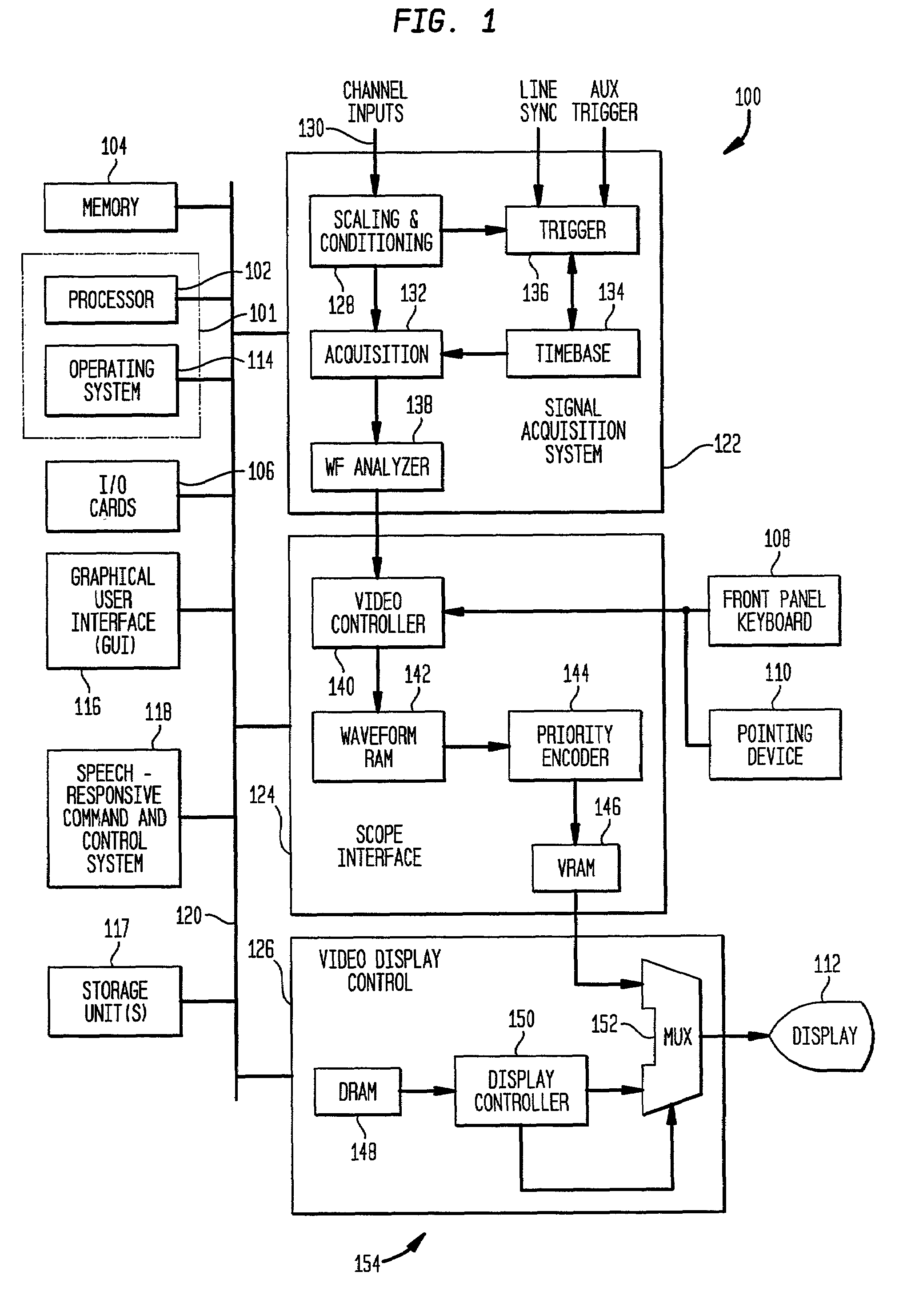
[0064]FIG. 1 is a functional block diagram of an exemplary digital oscilloscope suitable for implementing the present invention. Digital oscilloscope 100 is a commonly-available digital oscilloscope designed to acquire, analyze, and display a wide variety of signals generally in terms of signal voltage versus time. Although the present invention may be implemented in any oscilloscope, as will be described in detail below, digital oscilloscope 100 preferably includes a general purpose computer system on which software application programs may be executed, and integrated, specially programmed, special purpose hardware for performing signal acquisition, analysis and display functions.

[0065]Digital oscilloscope...


PUM


Abstract

A speech-responsive command and control system and methodology for use in a signal measurement system, enabling an operator to control certain features and functions of the oscilloscope without using manual or graphical controls. A speech-responsive command and control system includes a speech recognition engine constructed and arranged to validate digital voice signals in accordance with an associated grammar file defining command and control utterances for controlling the signal measurement system. A voice controlled measurement system controller is also included. This controller is constructed and arranged to control the signal measurement system in response to text utterances validated by the speech recognition engine. The grammar may include rules defining acceptable command and control utterances suitable for controlling the signal measurement system. The speech recognition engine generates, for valid utterances, a text utterance representing the recognized utterance to the voice-controlled measurement system controller. The text utterance may be an ASCII string. In one embodiment, the system includes a natural language speech application interface. The NLSAI is constructed and arranged to parse the valid text utterances to generate command parameters included in the valid text utterances based upon a predetermined corpus comprising a list of all valid command an control utterances. A method for controlling a signal measurement system in response to voice commands is also disclosed. The method includes the steps of: 1) receiving a command utterance generated by the operator; 2) digitizing the command utterance; 3) determining whether the digitized command utterance is a valid command and control utterance; and 4) generating a system command to cause the signal measurement system to perform a function in response to the valid command and control utterance. Preferably, the method also includes the step of: 5) displaying the command utterance on a display operatively coupled to the signal measurement system.

Description

[0001]This is a Continuation of application Ser. No. 09 / 386,531, filed on Aug. 30, 1999 now abandoned, the entire disclosure of which is incorporated herein by reference.BACKGROUND OF THE INVENTION[0002]1. Field of the Invention[0003]The present invention relates generally to a signal measurement systems and, more particularly, to voice controlled signal measurement systems.[0004]2. Related Art[0005]Conventional signal measurement systems such as digital oscilloscopes sample, record and display time-varying analog signals. Samples of an input signal are taken and quantized, and the resultant digital representations are stored in a waveform memory under the control of a sampling clock. The acquired data may be subsequently read out as locations in memory are sequentially addressed by a clock signal to provide digital data that can be converted to a time-varying output signal for a waveform display. The sampling clock may be operated at one of several selectable rates depending upon t...

Claims


Application Information

Patent Timeline
IPC IPC(8): G10L15/24G01R1/02G01R13/34G10L15/22G10L15/26
CPCG10L15/26G01R13/345G01R1/025G01R1/02G10L2015/221G10L2015/223
Inventor ALEXANDER, JAY AKARIN, MICHAEL J
Owner AGILENT TECH INC
Learn More