Centrifugal separation apparatus and method for separating fluid components

a technology of centrifugal separation and fluid components, which is applied in the direction of centrifuges, other medical devices, suction devices, etc., can solve the problems of unable to produce platelet products consistently (99% of the time), host of serious health risks, and inability to separate all white blood cells from platelets, so as to reduce the clumping of platelets

Inactive Publication Date: 2006-04-18
TERUMO BCT
View PDF122 Cites 68 Cited by
  • Summary
  • Abstract
  • Description
  • Claims
  • Application Information

AI Technical Summary

Benefits of technology

[0029]In another aspect, the invention includes a method of reducing clumping of platelets during separation of blood components. The method includes introducing blood components into a rotating separation vessel such that the blood components stratify in the separation vessel to form at least a radial outer layer including red blood cells, an intermediate layer including at least platelets, and a radial inner layer including low density substances. To substantially limit contact between the platelets and at least one of the radial inner and outer walls of the separation vessel, the radial outer layer of red blood cells is maintained between the intermediate layer and the radial outer wall of the separation vessel and / or the radial inner layer of low density substances is maintained between the intermediate layer and the radial inner wall of the separation vessel. This reduces platelet clumping.

Problems solved by technology

However, if a patient receives an excessive number of foreign white blood cells as contamination in a platelet transfusion, the patient's body may reject the platelet transfusion, leading to a host of serious health risks.
Centrifuges are effective at separating platelets from whole blood, however they typically are unable to separate all of the white blood cells from the platelets.
Historically, blood separation and centrifugation devices are typically unable to consistently (99% of the time) produce platelet product that meets the “leukopoor” standard of less than 5×10⁶ white blood cells for at least 3×10¹¹ platelets collected.
However, use of the porous filter introduces its own set of problems.
Conventional porous filters may be inefficient because they may permanently remove or trap approximately 5–20% of the platelets.
These conventional filters may also reduce “platelet viability,” meaning that once passed through a filter a percentage of the platelets cease to function properly and may be partially or fully activated.
In addition, porous filters may cause the release of brandykinin, which may lead to hypotensive episodes in a patient.
Porous filters are also expensive and often require additional time consuming manual labor to perform a filtration process.
Although porous filters are effective in removing a substantial number of white blood cells, they have drawbacks.
Otherwise, the activated platelets are likely to clog the filter.
Therefore, the use of at least some porous filters is not feasible in on-line processes.
Thus, some elutriation processes only permit separation in particle batches and require an additional fluid medium to transport particles.
This phenomenon mixes particles within the chamber and reduces the effectiveness of the separation process.
Particle mixing by particle density inversion is an additional problem encountered in some prior elutriation processes.
This particle turnover reduces the effectiveness of particle separation by elutriation.

Method used


Image

  • Centrifugal separation apparatus and method for separating fluid components
  • Centrifugal separation apparatus and method for separating fluid components
  • Centrifugal separation apparatus and method for separating fluid components

Examples


Embodiment Construction

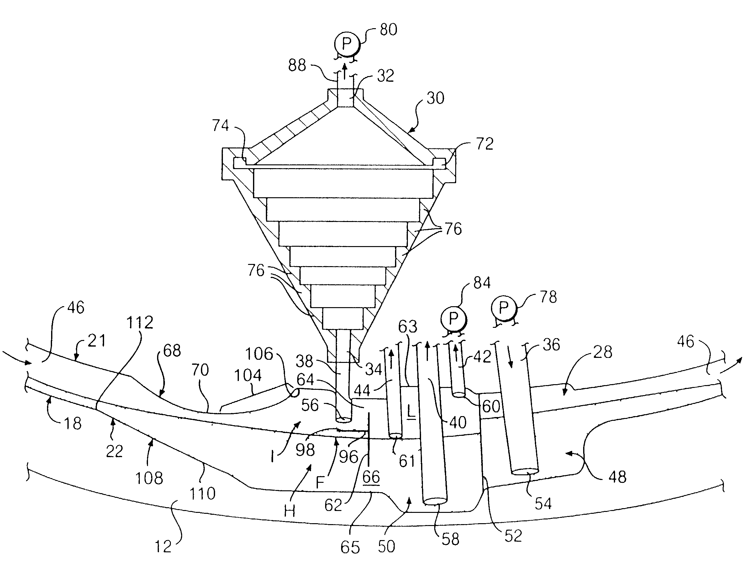
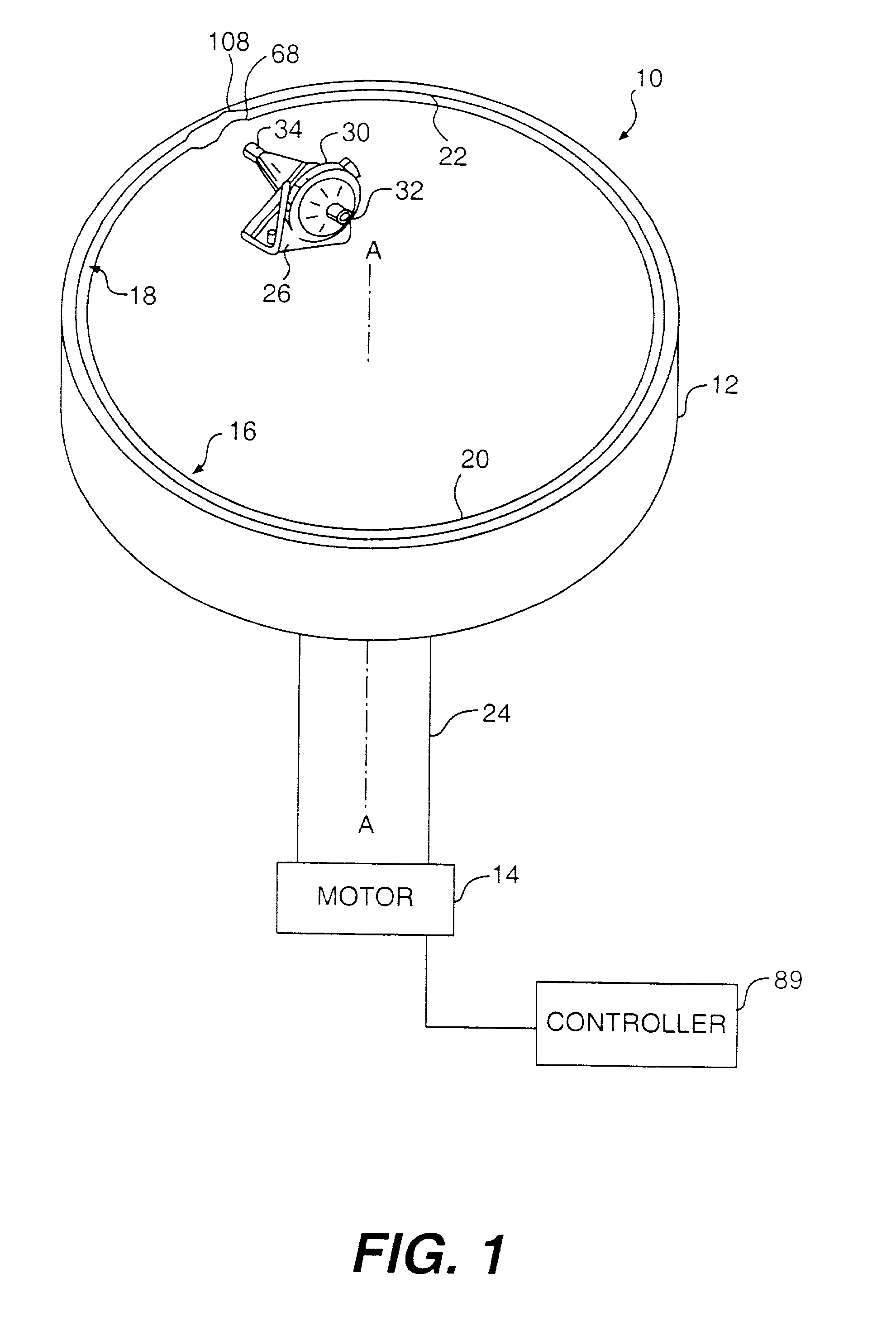
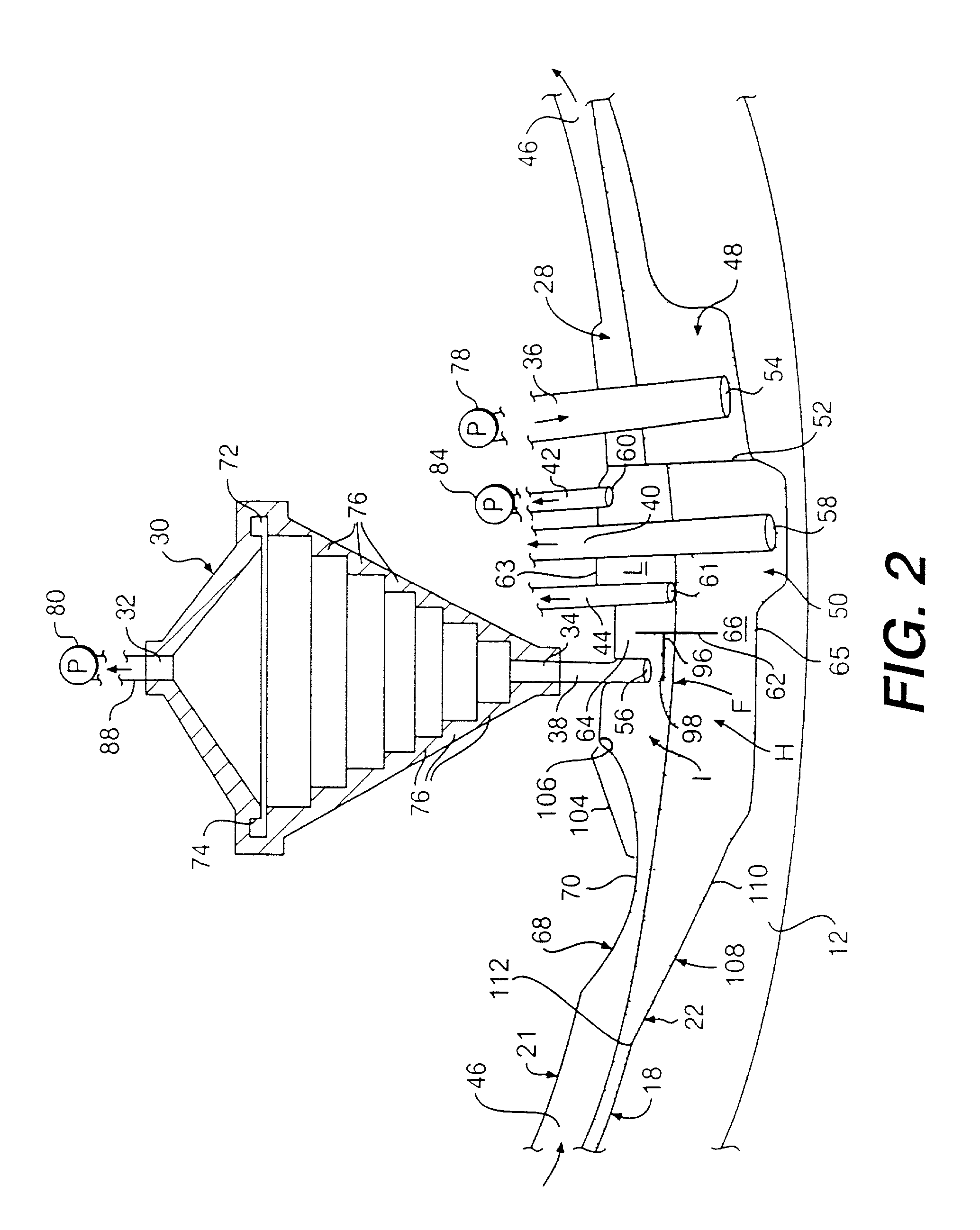
[0039]Reference will now be made in detail to the present preferred embodiments of the invention illustrated in the accompanying drawings. Wherever possible, the same reference numbers are used in the drawings and the description to refer to the same or like parts, and the same reference numerals with alphabetical suffixes are used to refer to similar parts.

[0040]The embodiments of the present invention preferably include a COBE® SPECTRA™ single stage blood component centrifuge manufactured by Cobe Laboratories of Colorado. The COBE® SPECTRA™ centrifuge incorporates a one-omega / two-omega sealless tubing connection as disclosed in U.S. Pat. No. 4,425,112 to Ito, the entire disclosure of which is incorporated herein by reference. The COBE® SPECTRA™ centrifuge also uses a single-stage blood component separation channel substantially as disclosed in U.S. Pat. No. 4,094,461 to Kellogg et al. and U.S. Pat. No. 4,647,279 to Mulzet et al., the entire disclosures of which are also incorporat...


PUM

PropertyMeasurementUnit
distanceaaaaaaaaaa
distanceaaaaaaaaaa
radiusaaaaaaaaaa

Abstract

An apparatus and method are provided for separating components of a fluid or particles. A separation vessel having a barrier dam is provided to initially separate an intermediate density components of a fluid, and a fluid chamber is provided to further separate these intermediate density components by forming an elutriative field or saturated fluidized particle bed. The separation vessel includes a shield for limiting flow into the fluid chamber of relatively high density substances, such as red blood cells. The separation vessel also includes a trap dam with a smooth, gradually sloped downstream section for reducing mixing of substances. Structure is also provided for adding additional plasma to platelets and plasma flowing from the fluid chamber. The system reduces clumping of platelets by limiting contact between the platelets and walls of the separation vessel.

Description

[0001]This is a continuation application of application Ser. No. 09 / 270,105, filed Mar. 16, 1999 now U.S. Pat. No. 6,334,842, which is incorporated herein by reference.BACKGROUND OF THE INVENTION[0002]1. Field of the Invention[0003]The present invention relates to an apparatus and method for separating components of a fluid. The invention has particular advantages in connection with separating blood components.[0004]This application is related to U.S. Pat. No. 5,674,173, issued on Oct. 7, 1997, U.S. patent application Ser. No. 08 / 676,039, filed on Jul. 5, 1996 (pending), and U.S. patent application Ser. No. 08 / 853,374, filed on May 8, 1997 (pending). The entire disclosures of U.S. Pat. No. 5,674,173 and U.S. patent application Ser. Nos. 08 / 676,039 and 08 / 853,374 are incorporated herein by reference.[0005]2. Description of the Related Art[0006]In many different fields, liquids carrying particle substances must be filtered or processed to obtain either a purified liquid or purified pa...

Claims


Application Information

Patent Timeline
Patent Type & Authority Patents(United States)
IPC IPC(8): B04B7/08G01N33/48A61M1/02A61M1/36B04B5/04G01N1/10G01N1/28
CPCA61M1/3693A61M1/3696B04B5/0442A61M2202/0427B04B2005/045B04B2005/0471
Inventor HLAVINKA, DENNISFELT, THOMAS J.
Owner TERUMO BCT
Why Eureka
Try Eureka