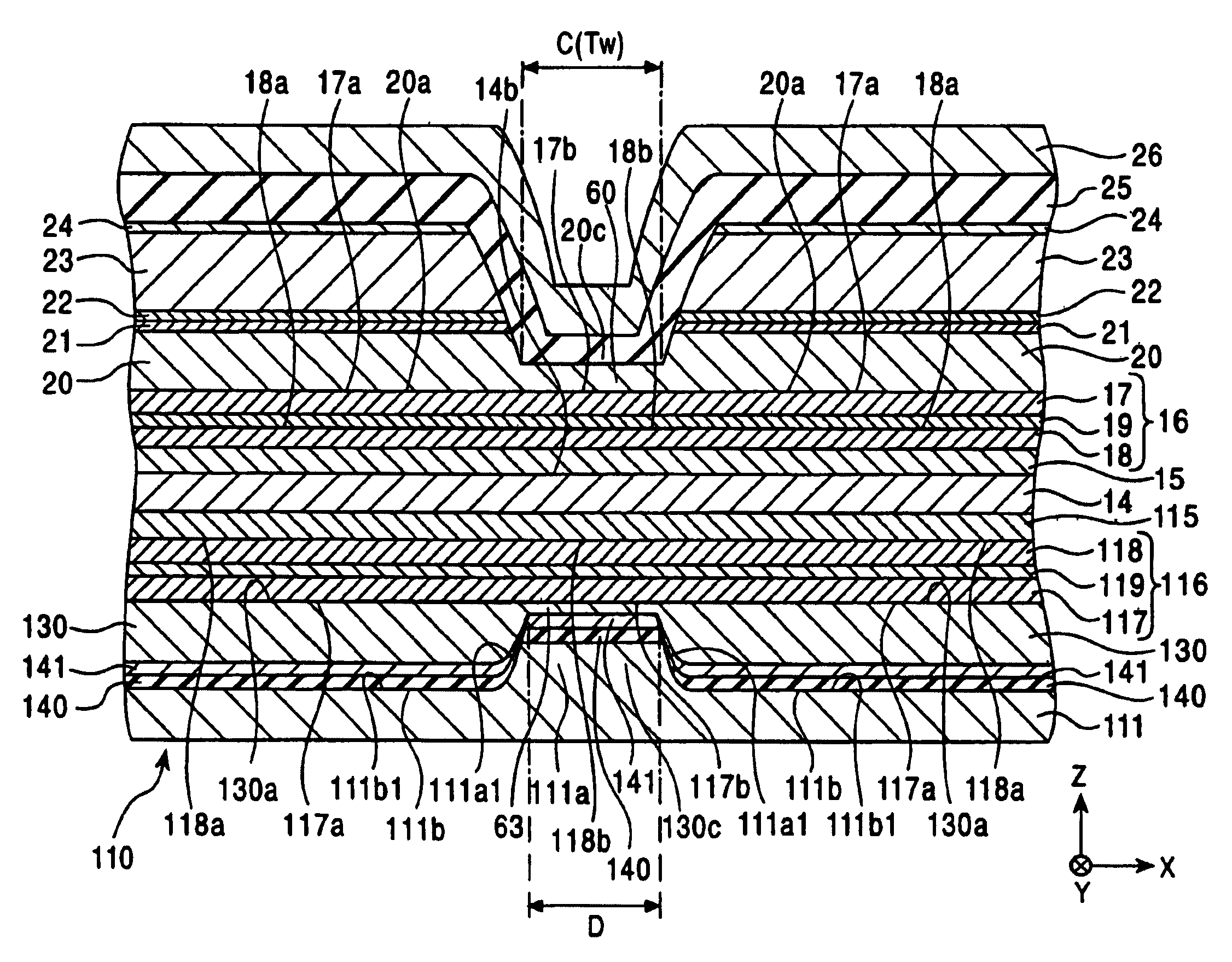
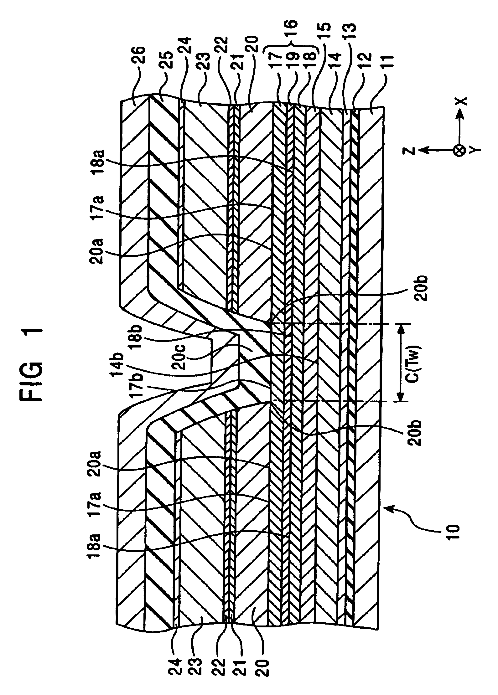
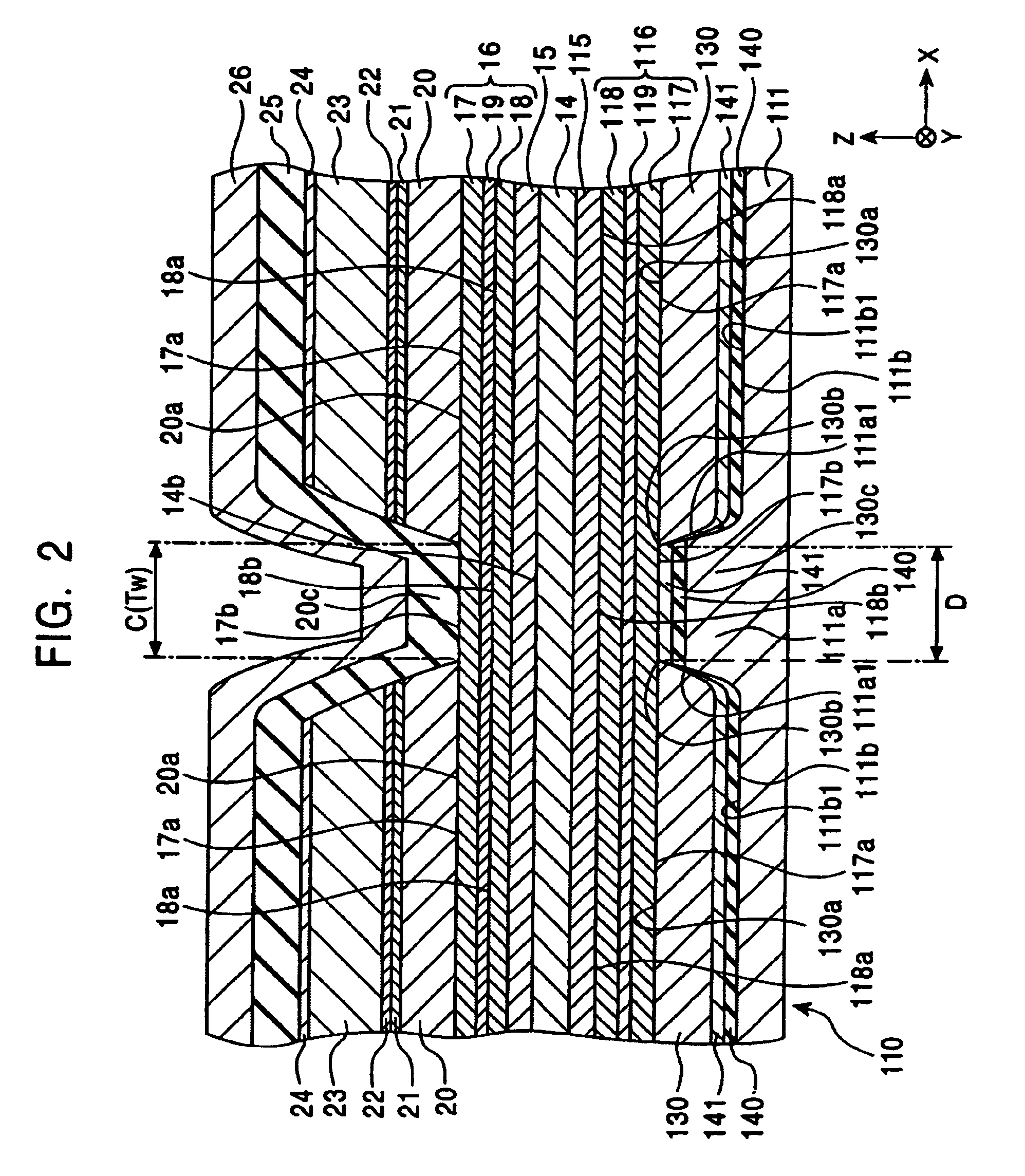
Magnetic sensor having free layer additionally provided with magnetic anisotropy by shape anisotropy

a free layer and magnetic anisotropy technology, applied in the field of magnetic sensors, can solve the problems of reducing the reproduction output, limiting the resolution, and increasing the distance between the upper shield layer and the lower shield layer, so as to simplify the structure of the entire element and reduce the thickness

Inactive Publication Date: 2006-04-18
TDK CORPARATION
View PDF12 Cites 19 Cited by
  • Summary
  • Abstract
  • Description
  • Claims
  • Application Information

AI Technical Summary

Benefits of technology

[0056]When a vertical bias layer is not provided, the structure of the entire element can be simplified, and in addition, an element having a smaller thickness can also be realized.

Problems solved by technology

Hence, the distance between the upper shield layer and the lower shield layer is increased, and as a result, there is a limit to improve the resolution.
Hence, a relatively large sense current cannot be prevented from being shunted from an electrode layer to the thin part, and as a result, a current loss occurs, thereby decreasing reproduction output.
In this case, as disclosed in Japanese Unexamined Patent Application Publication No. 2000-163717, when a thin antiferromagnetic layer, which generates exchange coupling, is present at the central portion of the fixed magnetic layer in the track width direction, the exchange coupling with the fixed magnetic layer at this thin part becomes unstable.
In particular, when the fixed magnetic layer is formed of a single magnetic layer, the magnetization may not be tightly fixed in many cases.
Even in a synthetic ferrimagnetic structure in which the fixed magnetic layer has a first and a second magnetic layer, which are magnetized in an antiparallel state by the RKKY coupling, when one of the magnetic layers is formed so as to be in contact with the antiferromagnetic layer, and the exchange coupling with the antiferromagnetic layer becomes unstable, the direction of magnetization of the magnetic layer in contact with the antiferromagnetic layer is reversed, and as a result, the fixed magnetization of the fixed magnetic layer becomes unstable.
As described above, according to the magnetic sensor disclosed in Japanese Unexamined Patent Application Publication No. 2000-163717, since the antiferromagnetic layer in a magnetic sensing region is intentionally formed thin, a phenomenon in which the fixed magnetization of the fixed magnetic layer becomes unstable as described above cannot be avoided.
However, in the structure in which Co films are provided on a buffer layer composed tantalum, as described above in Japanese Unexamined Patent Application Publication No. 8-7235, it was found that the direction of magnetization of the pinned ferromagnetic layer cannot be appropriately fixed.
In addition, in a related spin-valve type magnetic sensor, since a vertical bias layer is provided for stabilizing the direction of magnetization of the free magnetic layer, the multilayer structure thereof is complicated, and as a result, the manufacturing cost is increased.

Method used


Image

  • Magnetic sensor having free layer additionally provided with magnetic anisotropy by shape anisotropy
  • Magnetic sensor having free layer additionally provided with magnetic anisotropy by shape anisotropy
  • Magnetic sensor having free layer additionally provided with magnetic anisotropy by shape anisotropy

Examples


examples

[0217]By using magnetic sensors having the structures shown in FIG. 17 (example) and shown in FIG. 20 (comparative example), a unidirectional exchange bias magnetic field Hex* and a reproduction output (normalized output) were obtained.

[0218]FIG. 17 (example) is a partial cross-sectional view schematically showing a magnetic sensor when it is viewed from the face opposing a recording medium, and the film structure had a seed layer of 60 atomic percent of (Ni0.8Fe0.2) and 40 atomic percent of Cr (60 Å); a free magnetic layer of 80 atomic percent of Ni and 20 atomic percent of Fe (35 Å) / 90 atomic percent of Co and 10 atomic percent of Fe (10 Å); a nonmagnetic material layer of Cu (21 Å); a fixed magnetic layer [a second magnetic layer of 90 atomic percent of Co and 10 atomic percent of Fe (X Å) / an interlayer of Ru (9 Å) / a first magnetic layer of 90 atomic percent of Co and 10 atomic percent of Fe (Y Å)]; and antiferromagnetic layers of 50 atomic percent of Pt and 50 atomic percent of ...


PUM

PropertyMeasurementUnit
lengthaaaaaaaaaa
lattice spacingaaaaaaaaaa

Abstract

An intermediate region is formed at a central portion of an element in a track width direction, and an antiferromagnetic layer is not provided at the intermediate region. Accordingly, a sense current can be prevented from being shunted to the intermediate region, and as a result, improvement in reproduction output and strength against magnetic electrostatic damage can be realized. In addition, since the thickness of the central portion of the element is decreased, trend toward narrower gap can be realized. Furthermore, since the direction of magnetization of a free magnetic layer is oriented in the track width direction by shape anisotropy, means for orienting the magnetization is not necessary, and hence the structure and manufacturing method of the element can be simplified.

Description

BACKGROUND OF THE INVENTION[0001]1. Field of the Invention[0002]The present invention relates to magnetic sensors such as a spin-valve type thin film element mounted on hard disc devices or the like, and more particularly, relates to a magnetic sensor in which an exchange coupling region between a fixed magnetic layer and an antiferromagnetic layer is specifically defined.[0003]2. Description of the Related Art[0004]In a related spin-valve type magnetic sensor, a free magnetic layer, a nonmagnetic material layer, a fixed magnetic layer, and an antiferromagnetic layer are provided to form a multilayer structure, and the magnetization of the fixed magnetic layer is fixed in a predetermined direction. In addition, a vertical bias magnetic field is applied to each side of the free magnetic layer, and the direction of magnetization thereof is oriented so as to cross that of the fixed magnetic layer. In this type of magnetic sensor, a lower shield layer and an upper shield layer are provi...

Claims


Application Information

Patent Timeline
Patent Type & Authority Patents(United States)
IPC IPC(8): G11B5/127B32B3/02B32B15/04G01R33/09G11B5/39H01F10/16H01F10/32H01L43/08H01L43/10
CPCB32B3/02B32B15/04B82Y10/00B82Y25/00G01R33/093H01F10/3268G11B5/3903Y10T428/1157H01F10/123Y10T428/1193Y10T428/115Y10T428/1143
Inventor HASEGAWA, NAOYAUMETSU, EIJISAITO, MASAMICHIIDE, YOSUKE
Owner TDK CORPARATION
Why Eureka
Try Eureka