

Solid oxide fuel cell
a fuel cell and solid oxide technology, applied in the direction of cell components, final product manufacturing, sustainable manufacturing/processing, etc., can solve the problem that the electric conductivity of the first electrolyte layer cannot be conducted easily, and achieve the effect of avoiding the reduction in the total electric conductivity of the first electrolyte layer, facilitating production, and optimizing the total electric conductivity of the solid electrolyte layer comprising the first and second electrolyte layers
- Summary
- Abstract
- Description
- Claims
- Application Information
AI Technical Summary
Benefits of technology
Problems solved by technology
Method used
Image

Examples
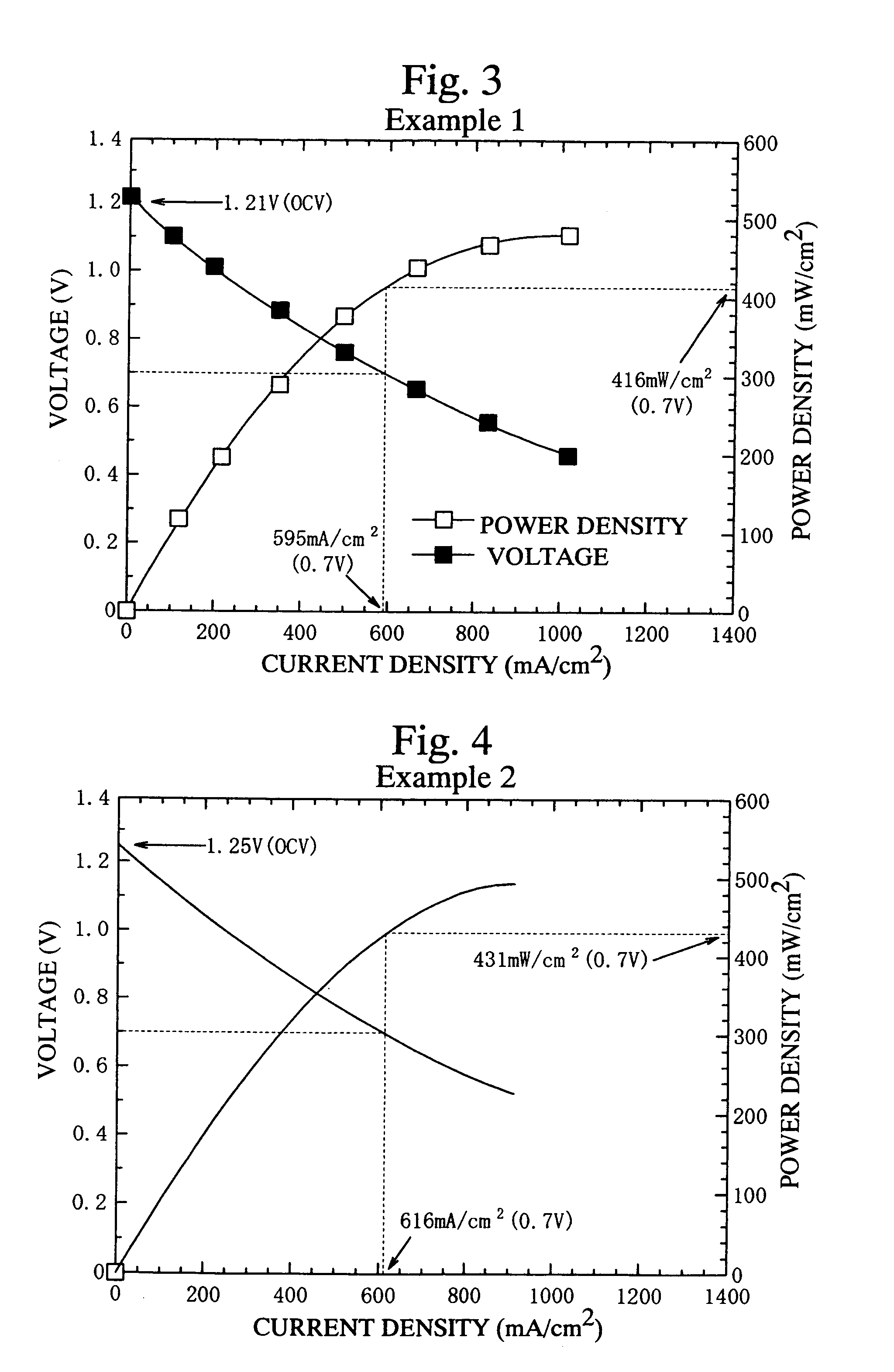
example 1
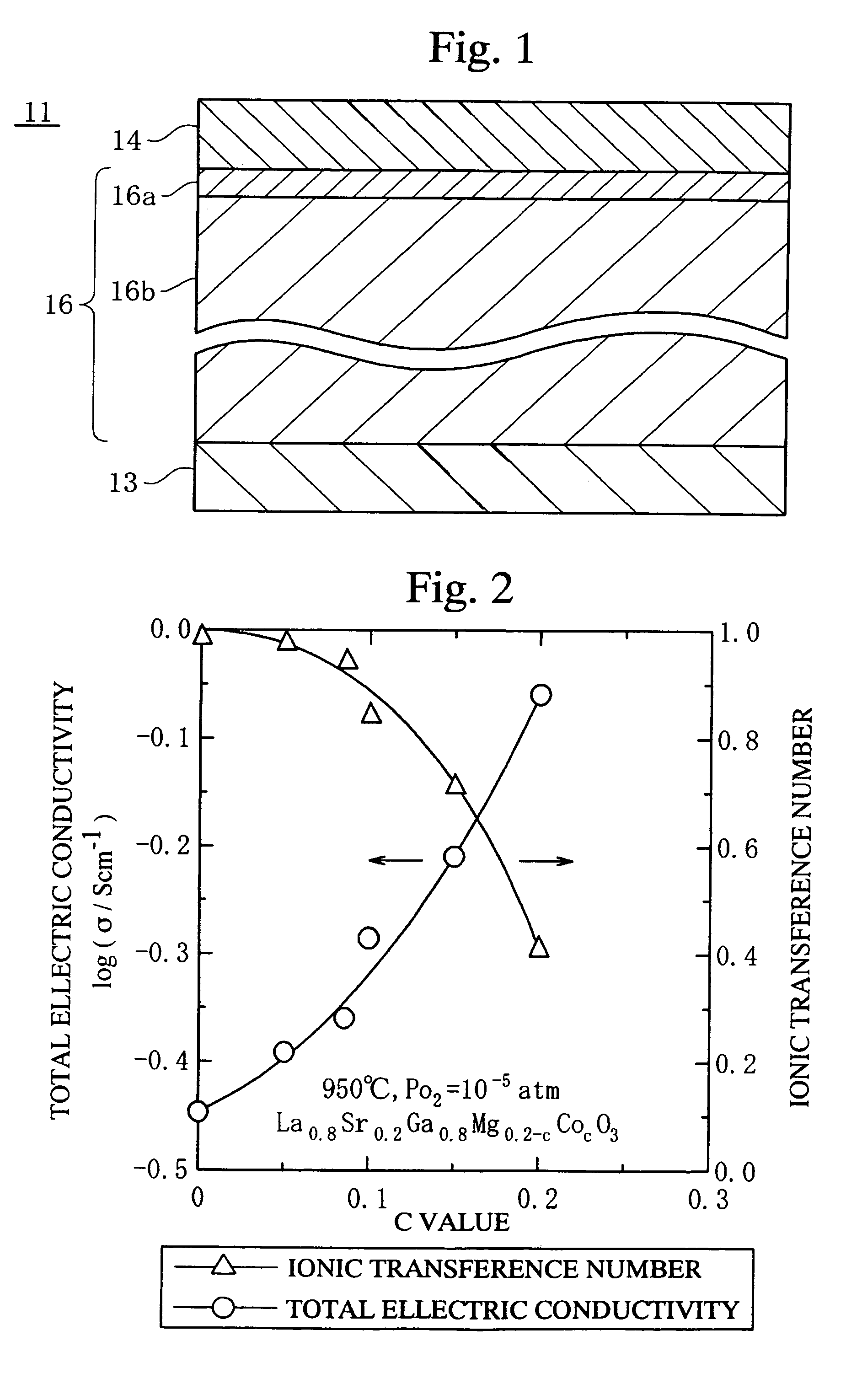
[0061]The fuel cell 11 as shown in FIG. 1, which comprises the fuel electrode layer 13 having a diameter of 75 mm and a thickness of 60 μm, the solid electrolyte layer 16 having a diameter of 75 mm and a thickness of 100 μm, and the air electrode layer 14 having a diameter of 75 mm and a thickness of 40 μm, was produced.
[0062]The air electrode layer 14 was made of an oxide ionic mixed conductor represented by Sm0.5Sr0.5CoO3−d. The fuel electrode layer 13 was made of a mixture containing Ni and a compound represented by Ce0.8Sm0.2O2.
[0063]The first electrolyte layer 16a was made of a compound represented by La0.8Sr0.2Ga0.8Mg0.15Co0.05O3−d. The second electrolyte layer 16b was made of an oxide ionic mixed conductor represented by La0.75Sr0.15Ga0.775Mg0.125Co0.1O3−d. The solid electrolyte layer 16 was formed by the following steps. First, oxide powder materials were mixed to obtain the above compositions of the first and second electrolyte layers 16a and 16b. Then, the oxide mixtures w...
example 2
[0065]The first and second electrolyte layers 16a and 16b were produced by coating the alumina setter on a green sheet having the composition represented by La0.9Sr0.1Ga0.8Mg0.12Co0.08O3−d and sintering. The first electrolyte layer 16a was formed at the surface layer of the green sheet, which was coated with the alumina setter. The remainder of the green sheet was the second electrolyte layer 16b. The thickness of the solid electrolyte layer 16 comprising the first and second electrolyte layers 16a and 16b was 100 μm. The fuel cell 11 was formed using the solid electrolyte layer 16, similar to Example 1.
[0066]The quantity of the elements in the solid electrolyte layer 16 of the fuel cells formed in this Example were analyzed by the Electron Probe Microanalysis (EPMA) method. The results are shown in Table 1. Moreover, “d” in Table 1 indicates the depth from the surface of the solid electrolyte layer 16, which was coated with the alumina setter.
[0067]
TABLE 1Depth from the surface of ...
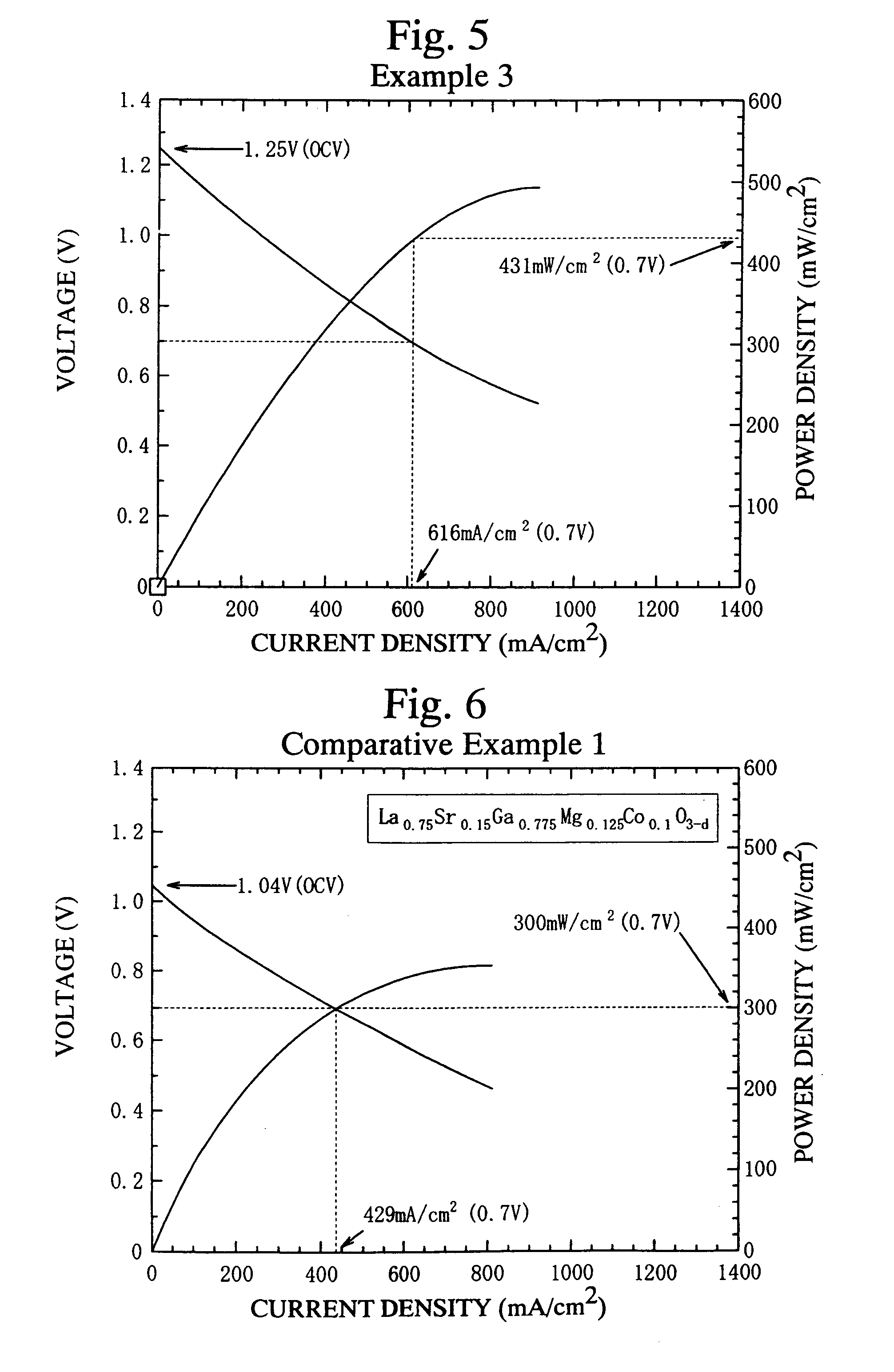
example 3
[0069]A fuel cell 11 was produced in a manner identical to that of Example 1, except the fuel electrode layer 13 was sintered onto the first electrolyte layer 16a, and the air electrode layer 14 was sintered onto the second electrolyte layer 16b.
PUM
| Property | Measurement | Unit |
|---|---|---|
| thickness | aaaaa | aaaaa |
| temperatures | aaaaa | aaaaa |
| temperatures | aaaaa | aaaaa |
Abstract
Description
Claims
Application Information