
Wideband optical fiber amplifier

a wideband optical fiber and amplifier technology, applied in the direction of wave amplification devices, electrical equipment, laser details, etc., can solve the problems of increasing the loss of optical signals, the loss of the entire optical power generated, and the lack of high-power semiconductor lasers in the wavelength band of 1560 nm up to date, so as to improve the noise figure and improve the amplification efficiency

Inactive Publication Date: 2006-04-25
SAMSUNG ELECTRONICS CO LTD
View PDF11 Cites 3 Cited by
  • Summary
  • Abstract
  • Description
  • Claims
  • Application Information

AI Technical Summary

Benefits of technology

[0036]Accordingly, the present invention has been made to overcome the above-mentioned problems and provides additional advantages, by providing a wideband optical fiber amplifier which causes both a noise figure and an amplification efficiency to be improved.
[0037]One aspect of the present invention to provide a pumping light source of a thulium-doped optical fiber that is easily integrated in applications and the like.

Problems solved by technology

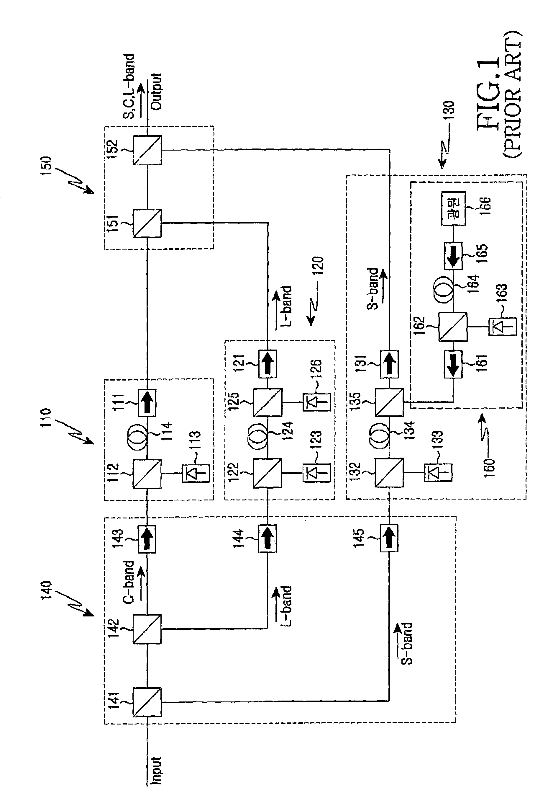
However, the conventional wavelength band splitting unit has a problem in that it makes use of too many components in order to divide optical signals based on each wavelength band, so that insertion loss of the optical signals is increased before the optical signals are inputted into respective optical fiber amplifying units.
The insertion loss means the loss of the entire optical power generated while optical signals pass through a plurality of components, and such insertion loss acts as a factor in deteriorating a noise figure of the wideband optical fiber amplifier.
However, a high power semiconductor laser having the wavelength band of 1560 nm is still not yet available up to date.
Thus, before the optical signals are inputted into each optical fiber amplifying unit, insertion loss of the respective optical signals is greatly increased.
Due to the foregoing factors, the conventional wideband optical fiber amplifier has a problem in that its noise figure and amplification efficiency are deteriorated.

Method used


Image

  • Wideband optical fiber amplifier
  • Wideband optical fiber amplifier
  • Wideband optical fiber amplifier

Examples


Embodiment Construction

[0043]Hereinafter, preferred embodiments of the present invention will be described in detail with reference to the accompanying drawings. For the purposes of clarity and simplicity a detailed description of known functions and configurations incorporated herein will be omitted when they may obscure the subject matter of the present invention.

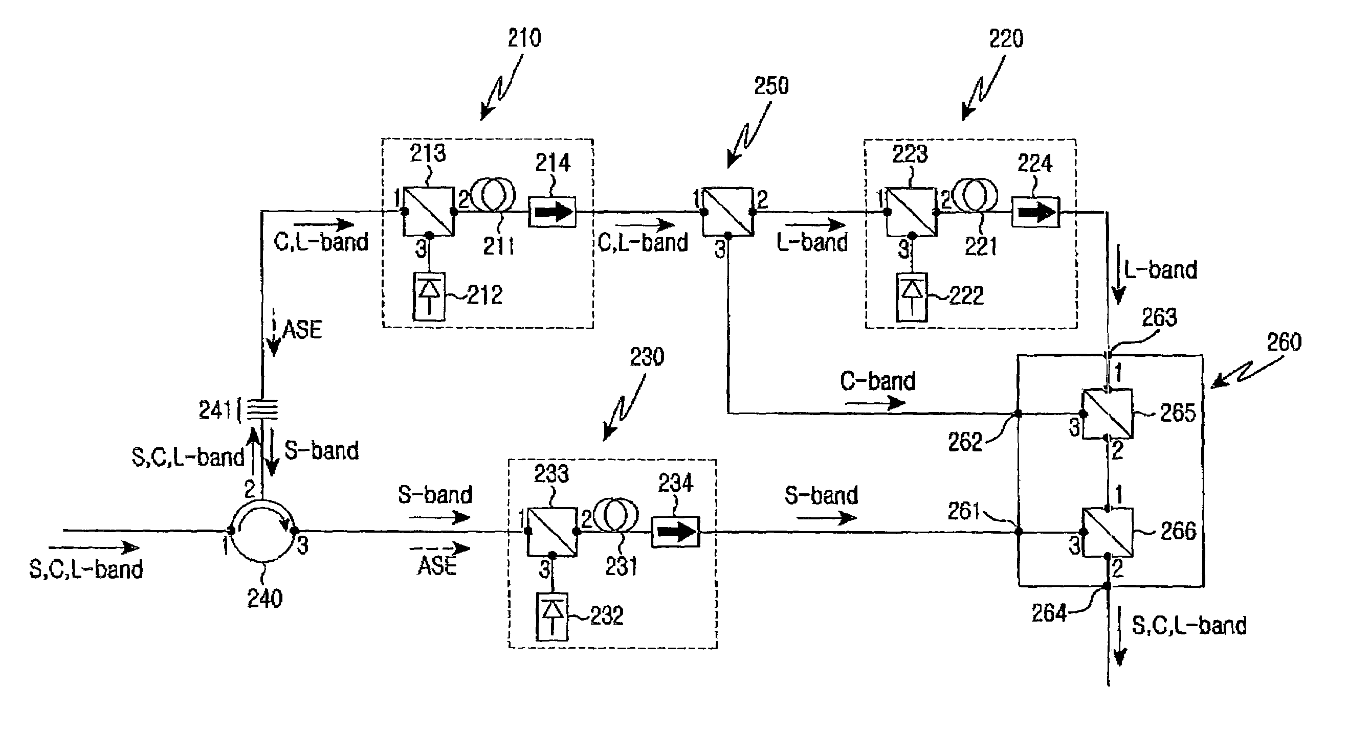
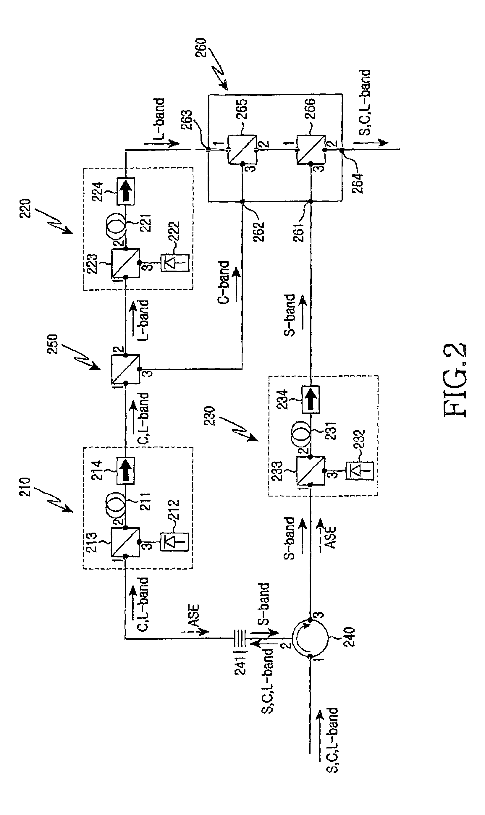
[0044]FIG. 2 shows a construction of a wideband optical fiber amplifier according to a preferred embodiment of the present invention. As shown, the wideband optical fiber amplifier includes a circulator 240, an optical fiber grating 241, an outputting unit 260 for outputting each amplified optical signal to one terminal, a first optical fiber amplifying unit 210 for amplifying C- and L-band optical signals, a second optical fiber amplifying unit 220 for amplifying L-band optical signals, a third optical fiber amplifying unit 230 for amplifying S-band optical signals, and a wavelength selective splitter 250 for coupling the first optical fiber a...


PUM


Abstract

The wideband optical fiber optical includes a circulator. In addition the amplifier outputs the amplified spontaneous emission (ASE) and the S-band optical signals. At least one optical fiber grating is used for passing the C- and L-band optical signals. A wavelength selective splitter outputs the L-band optical signal. A first optical fiber amplifying unit connected with the optical fiber grating and the first port of the wavelength selective splitter, for amplifying the C- and L-band optical signals and for outputting the ASE to the optical fiber grating. A second optical fiber amplifying unit for amplifying the L-band optical signals inputted from the second port of the wavelength selective splitter and for outputting the amplified L-band optical signals to the third terminal of the outputting unit. A third optical fiber amplifying unit amplifies the S-band optical signals input from the third port of the circulator, and outputs the amplified S-band optical signals to the first terminal of the outputting unit.

Description

CLAIM OF PRIORITY[0001]This application claims priority to an application entitled “Wideband Optical Fiber Amplifier,” filed in the Korean Intellectual Property Office on May 20, 2003 and assigned Ser. No. 2003-31969, the contents of which are hereby incorporated by reference.BACKGROUND OF THE INVENTION[0002]1. Field of the Invention[0003]The present invention relates to an optical fiber amplifier. More particularly, the present invention relates to a wideband optical fiber amplifier having an optical fiber doped with a rare earth element, thereby having a capability to amplify optical signals having a wide wavelength band.[0004]2. Description of the Related Art[0005]Wavelength division multiplexing (WDM) is a technique that allows for increases in transmission capacity per optical fiber. The increase in capacity is due to transmitting and receiving a plurality of channels, which are multi-divided to have different wavelengths, through a single optical fiber. Optical communication n...

Claims


Application Information

Patent Timeline
IPC IPC(8): H01S3/00H01S3/10H04B10/291
CPCH04B10/291H01S3/10
Inventor HWANG, SEONG-TAEKOH, YUN-JE
Owner SAMSUNG ELECTRONICS CO LTD
Learn More