Apparatus and method for controlling polarization in an optical communications medium

Active Publication Date: 2006-04-25
II VI DELAWARE INC
View PDF26 Cites 9 Cited by
  • Summary
  • Abstract
  • Description
  • Claims
  • Application Information

AI Technical Summary

Benefits of technology

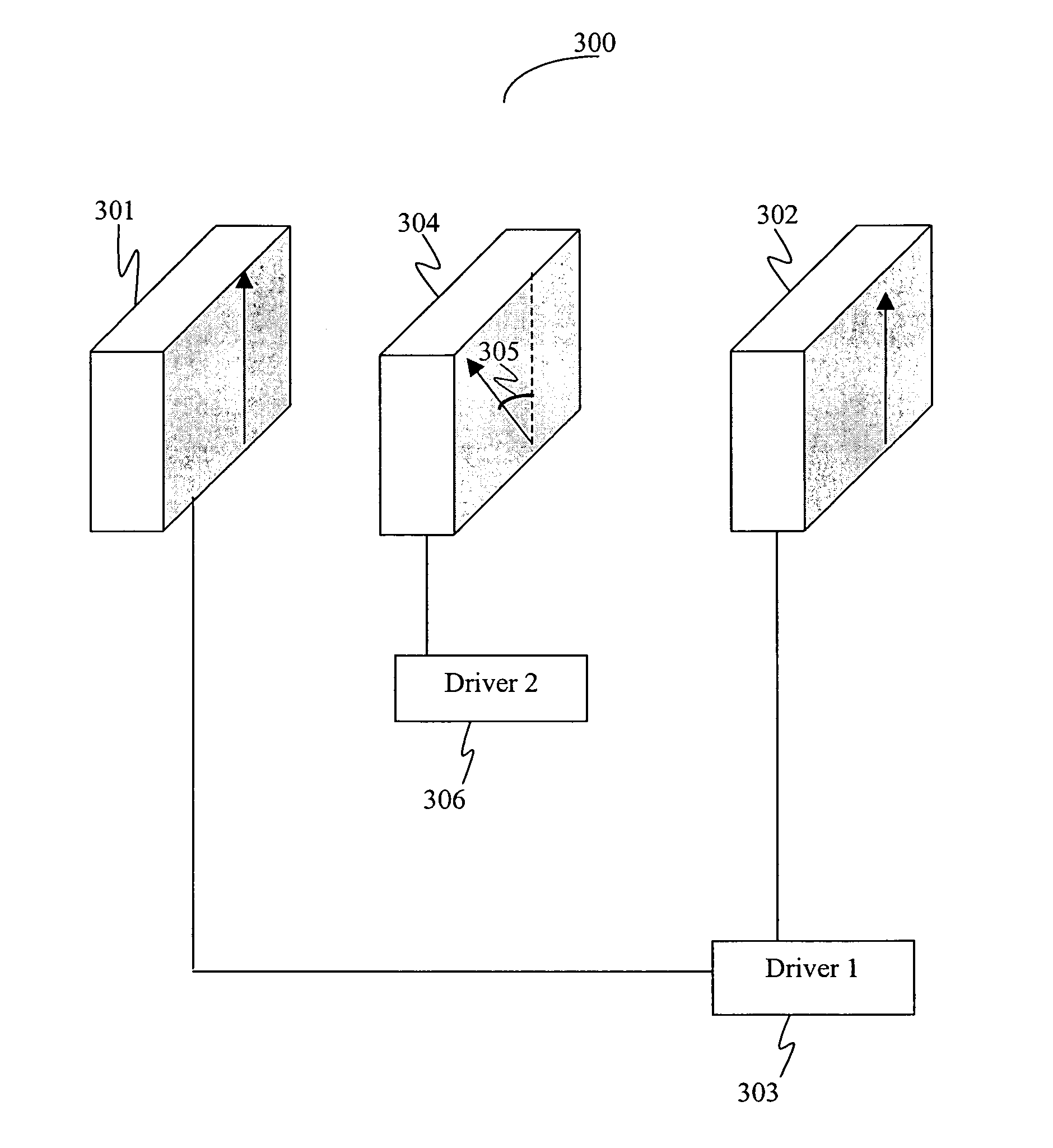
[0016]The invention includes a polarization controller and method for controlling such devices. In one embodiment of the invention, a polarization controller comprises a first element having a first optical axis and configured to receive light having a first phase, a second element having a second optical axis and configured to emit the light having a second phase, a third element having a third optical axis where at least a portion of the third element is interstitial to the first element and the second element, a first driver coupled to the first and the second element to reset the third element, and a second driver coupled to the third element. In some embodiments, liquid crystals are used as a constituent of at least one of the optical elements for providing control of polarization with relatively low operating voltages at relatively low cost. By proper arrangement (e.g., orthogonal alignments) of such liquid crystal-based wave-plates, the non-linear effects of the transient processes can be canceled.
[0017]In another embodiment, an exemplary polarization controller further comprises a drive-control module configured to cause the second driver to generate the second control signal having a first char

Problems solved by technology

In particular, these factors give rise to fiber birefringence, which can unpredictably change the states of polarization (SOP) of an optical signal traveling in a fiber, especially in a single-mode fiber.
But these reset cycles generally gives rise to periods of unacceptable data loss.
While these combined, cascaded devices permit substantially endless (reset-free) operation overall, individual constituent elements within traditional polarization control devices still require occasional reset cycles.
Although the reset cycles can be performed without affecting the overall polarization transformation (i.e., quasi-endless polarization control), these devices generally require complicated, computer-controlled driving algorithms for proper operation, which generally results in a slow response to fluctuations in SOP.
This approach, however, tends to result in slow resetting of polarization controller elements, which in turn results in suboptimal control of SO

Method used


Image

  • Apparatus and method for controlling polarization in an optical communications medium
  • Apparatus and method for controlling polarization in an optical communications medium
  • Apparatus and method for controlling polarization in an optical communications medium

Examples


Example

[0036]Like reference numerals refer to corresponding parts throughout the several views of the drawings.

DETAILED DESCRIPTION OF SPECIFIC EMBODIMENTS

[0037]The present invention provides a number of polarization controller devices, and methods for resetting polarization controller devices. In one embodiment of the present invention, an exemplary polarization controller device includes a stack of variable polarization converters formed with twisted nematic (TN) liquid crystal cells. In another embodiment of the present invention, an exemplary polarization controller device includes cascaded wave plates, where each wave plate has a fixed optical axis and is composed of birefringent liquid crystal material. According to the present invention, the polarization controller performs general polarization transformations from any arbitrarily varying optical input SOP into any arbitrary output SOP by adjusting either the phase retardation of variable wave plates or the rotation angle of polariz...


PUM


Abstract

An exemplary polarization controller includes a first optical element having a first optical axis and configured to receive light having a first phase, a second optical element having a second optical axis and configured to emit the light having a second phase, and a third element having a third optical axis. At least a portion of the third element is interstitial to the first element and the second element. The exemplary controller also includes at least two drivers, both of which can operate in accordance with an exemplary method of present invention.

Description

BRIEF DESCRIPTION OF THE INVENTION[0001]The present invention relates to optics, fiber optics, and optical communication systems. More particularly, the present invention relates to polarization controllers having application in communications, optical detection, optical instrumentation and other related areas.BACKGROUND OF THE INVENTION[0002]Temperature fluctuations, physical stresses, and other environmental conditions affect the fibers of an optical communication system. In particular, these factors give rise to fiber birefringence, which can unpredictably change the states of polarization (SOP) of an optical signal traveling in a fiber, especially in a single-mode fiber. These changes in the SOP are manifested as fading of the optical signal at the output end of a fiber (i.e., polarization dependent loss (PDL)) and, in some instances, polarization mode dispersion (PMD) loss.[0003]To correct the polarization state of optical signals emerging from an optical fiber, some convention...

Claims


Application Information

Patent Timeline
IPC IPC(8): G02F1/13363
CPCG02F1/0136G02F1/13G02F2001/133638G02F1/133638
Inventor KELLY, JACK ROBERTLIU, XUEWU
Owner II VI DELAWARE INC
Why Eureka
Try Eureka