Hybrid composite of silicone and organic resins

Inactive Publication Date: 2006-05-02
MASSACHUSETTS INST OF TECH +1
View PDF6 Cites 32 Cited by
  • Summary
  • Abstract
  • Description
  • Claims
  • Application Information

AI Technical Summary

Benefits of technology

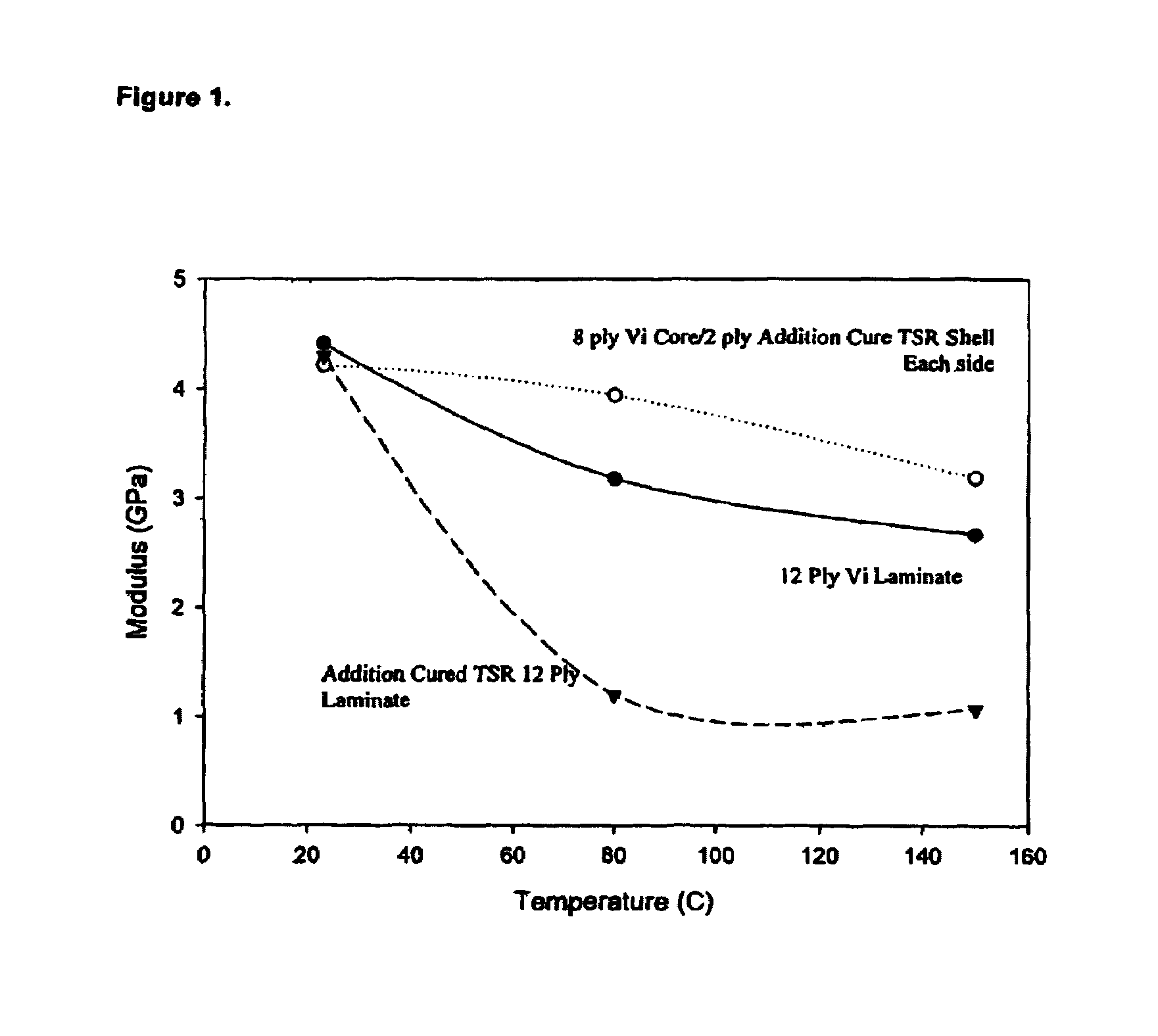
[0008]A fiber reinforced composite including a plurality of layers of fibers, each layer being impregnated with a resin. The plurality of layers includes in combination a layer(s) of an addition cured or condensation cured silicone resin and a layer(s) of an organic resin. The layers form a hybrid composite having a higher modulus retention at elevated temperatures than the silicone resin alone, having other mechanical properties similar to the organic resin composite, but exhibiting much enhanced thermal resistance and reduced flammability.

Problems solved by technology

Woven carbon fiber mats offer a higher modulus reinforcing media but they are more expensive than glass fibers.

Method used


Image

  • Hybrid composite of silicone and organic resins

Examples


reference example 1

[0039]Three Point Flexural Testing

[0040]The three point bending test was performed on an Instron 4500 per ASTM standard D 790-961. The cured resin specimens prepared in the Examples described below were cut into 5.08 cm×1.27 cm specimens using a band saw. The specimens were then machined to a thickness of 0.25 cm and polished. The specimens were tested using a cross head speed of 1 mm / min and a support span of 3.81 cm.

[0041]During testing, force-displacement curves were recorded. The toughness of the cured resin was obtained as the area under the stress-strain curves. The flexural strength was calculated using the peak force as:

S=3PL / 2bd2

[0042]where S is the stress in the outer surface at the mid span, P the maximum load, L the support span, and b and d are the width and thickness of the beam. The maximum strain was calculated, using the maximum displacement, as:

ε=6Dd / L2

[0043]where ε is the strain at break and D is the maximum displacement. The slope of the steepest initial straight...

reference example 2

[0044]Fracture Toughness Testing

[0045]The plane strain fracture toughness, Klc, was obtained per ASTM D 5045-96, and the critical strain energy release rate, Glc, was calculated from Klcbased on Linear Elastic Fracture Mechanics (LEFM) assumptions. 5.08cm×0.95 cm samples were cut using a band saw and a notch was cut at the center of the specimen. A natural crack extending from the root of the notch to about half of the width was produced by gently tapping a sharp razor blade into the notch. Samples were conditioned at 73° C. for at least twenty-four hours before testing to allow full relaxation of deformation. The displacement rate of the test was 10 mm / minute with a support span of 3.81 cm.

Klc=(P / (BW1 / 2))f(x)

[0046]where P is the highest load and:

f(x)=6x1 / 2(1.99−x(1−x)(2.15−3.93x+2.7x2)) / ((1+2x)(1−x)3 / 2)

[0047]where x is the pre-crack to specimen width ratio, a / W. After the test the pre-crack length was measured. Only those specimens with a value between 0.45 to 0.55 were considered ...

reference example 3

[0051]Dynamic Mechanical Analysis

[0052]Dynamic mechanical analysis was carried out on a TA Instrument DMA 2980. A specimen 20 mm long, 4 mm wide and 1 mm thick was mounted in two grips 14 mm apart. The specimen was then subjected to a sinusoidal tensile displacement at a frequency of 1 Hertz. The tension was measured and the storage and loss moduli and the loss factor were calculated. The tests were performed at temperatures ranging from −150 to 400° C. All tests were performed in a nitrogen environment with a gas flow rate of 200 ml / min.


PUM

PropertyMeasurementUnit
Temperatureaaaaaaaaaa

Abstract

A fiber reinforced composite including layers of fibers, each layer being impregnated with a resin. The layers include in combination a layer of an addition cured silicone resin and a layer of an organic resin. The layers form a hybrid composite having a higher modulus retention at elevated temperatures than the addition cured silicone resin alone. The hybrid composite's mechanical properties are similar to the organic resin composite, but demonstrate enhanced thermal resistance and reduced flammability.

Description

FIELD OF THE INVENTION[0001]This invention pertains to silicone resin based composites. More specifically, this invention relates to resin composites having a rigid silicone matrix resin and an organic resin.BACKGROUND OF THE INVENTION[0002]Fiber reinforced, silicone matrix resin composites find many applications in non-structural, semi-structural and structural components. The fiber reinforcement often takes the form of woven fiberglass fabrics. Woven carbon fiber mats offer a higher modulus reinforcing media but they are more expensive than glass fibers. Other fiber compositions such as aramid, nylon, polyester and quartz fibers may be used. Other fibrous forms, such as non-woven mats and layers of loose fibers, may also be used in silicone resin based composite applications.[0003]A large family of silicone matrix resins is available for composite applications. Such resins are typically highly cross-linked polymer molecules in cured form. They are substantially rigid materials dis...

Claims


Application Information

Patent Timeline
IPC IPC(8): B32B13/12B32B27/04B32B27/08H05K1/03
CPCB32B27/04B32B27/08H05K1/036H05K2201/0162H05K1/0366Y10T428/31855Y10T428/31663Y10T428/31667Y10T428/31942Y10T428/31511Y10T428/31935B32B2305/076B32B2260/046B32B2260/021B32B5/26B32B2307/3065B32B2305/024B32B5/024B32B5/022B32B2262/101B32B2262/106B32B2262/0276B32B2262/0261B32B2262/0269B32B3/12B32B2315/085
Inventor ZHU, BIZHONGREESE, HERSCHEL H.KATSOULIS, DIMITRIS E.KERYK, JOHN R.WU, YUHONGMCGARRY, FREDERICK J.
Owner MASSACHUSETTS INST OF TECH
Why Eureka
Try Eureka