
Digital to analog converter

a digital to analog converter technology, applied in the field of radar systems, can solve the problems of low frequency of the converter, difficult filtering, and inability to provide a suitable level of accuracy for many applications, and achieve the effects of reducing noise, improving transient response, and reducing nois

Active Publication Date: 2006-05-02
VALEO RADAR SYST
View PDF3 Cites 94 Cited by
  • Summary
  • Abstract
  • Description
  • Claims
  • Application Information

AI Technical Summary

Benefits of technology

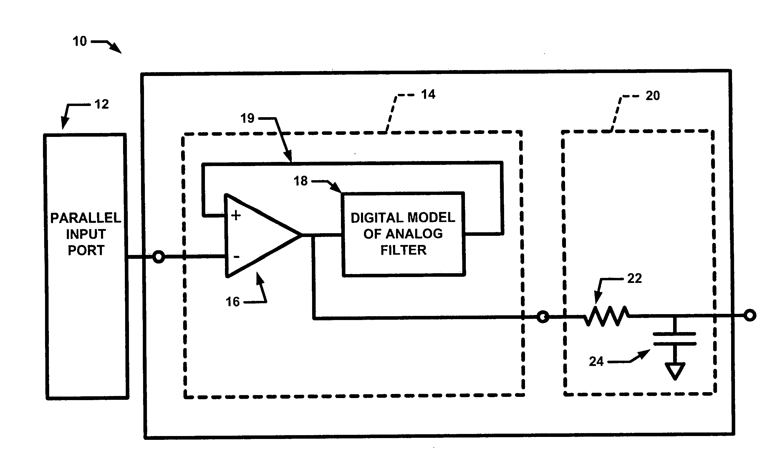
[0008]With this particular arrangement, a DAC having improved accuracy for a given clock rate and a given analog filter is provided. The comparator provides an output signal having a value dependent upon the values of the input signal and the feedback signal provided by the digital model of the analog filter. By providing the DAC with a digital feedback loop which includes a digital implementation (e.g. a digital model) of an analog filter and a comparator which compares the value of a digital input (or reference) signal to the value of the signal from the digital model of the analog filter, a DAC having a decreased amount of noise and an improved transient response is provided. By adding the digital model of the analog filter to the feedback loop, the digital processor is provided having a high pass filter characteristic. This approach reduces the amount of noise in the DAC. By matching the filter characteristics provided by the digital model of the analog filter to the filter characteristics of the analog filter, the transient response characteristics of the analog filter are reduced. Thus, the digital modeling of the analog filter improves the overall performance of the DAC. In one embodiment, the DAC is provided as a relatively low-cost, accurate, single bit DAC used in an automotive radar system. It should be appreciated that the general function provided by the comparator (i.e. comparing the value of the feedback signal to the value of the digital input signal and proving an output value based upon which is larger) can be also be accomplished by utilizing a subtractor circuit and a quantizer circuit.
[0010]With this particular arrangement, a technique for providing an analog waveform for modulating RF signals is provided. By providing a digital model of the analog filter in a feedback loop and by matching the digital filter characteristics of the model to the filter characteristics of the analog filter, a digital to analog converter which decreases the amount of noise and improves transient response is provided. The amount of noise is decreased because by adding the filter to the feedback loop, a processor is provided having a high pass filter characteristic. Thus, by including a digital model of an analog filter in a digital feedback loop with a comparator, DACs operating in accordance with the technique can provide relatively accurate waveforms which are suitable for use with RF signals in radar systems, including but not limited to automotive radar systems. It should be appreciated that the compare operation (i.e. comparing the value of the feedback signal to the value of the digital input signal and proving an output value based upon which is larger) can be also be accomplished by utilizing a subtractor and a quantizer circuit.

Problems solved by technology

Although it is desirable to provide relatively accurate analog waveforms, it is also sometimes desirable to provide low cost systems.
The switching noise generated by this converter contains low frequencies, which are difficult to filter.
Thus, while PWM converters are relatively simple and inexpensive, they also do not provide a suitable level of accuracy for many applications.
Thus, while DSM converter techniques typically provide a desired level of accuracy, they are relatively sophisticated and thus relatively expensive.
They also typically require a relatively high clock rate.

Method used


Image

  • Digital to analog converter
  • Digital to analog converter
  • Digital to analog converter

Examples


Embodiment Construction

[0016]Referring now to FIG. 1, a single bit digital-to-analog converter (DAC) 10 has an input port 10a, here provided as a parallel input port adapted to receive a digital input signal and an output port 10b at which an analog output signal is provided. The DAC 10 includes a digital processor 14.

[0017]The digital processor 14 includes one or more digital processing elements which may be implemented using a variety of different techniques including but not limited to as a plurality of logic gates, as an application specific integrated circuit (ASIC), as a field programmable gate array (FPGA) or as a microprocessor.

[0018]The digital processor 14 is programmed or otherwise provided to implement a comparator 16 and a filter 18 (also referred to herein as a “digital model of an analog filter” or more simply as a “digital filter” or a “digital implementation of a filter”). The phrase digital model of an analog filter, or any variant thereof, is intended to cover any discrete time model or...


PUM


Abstract

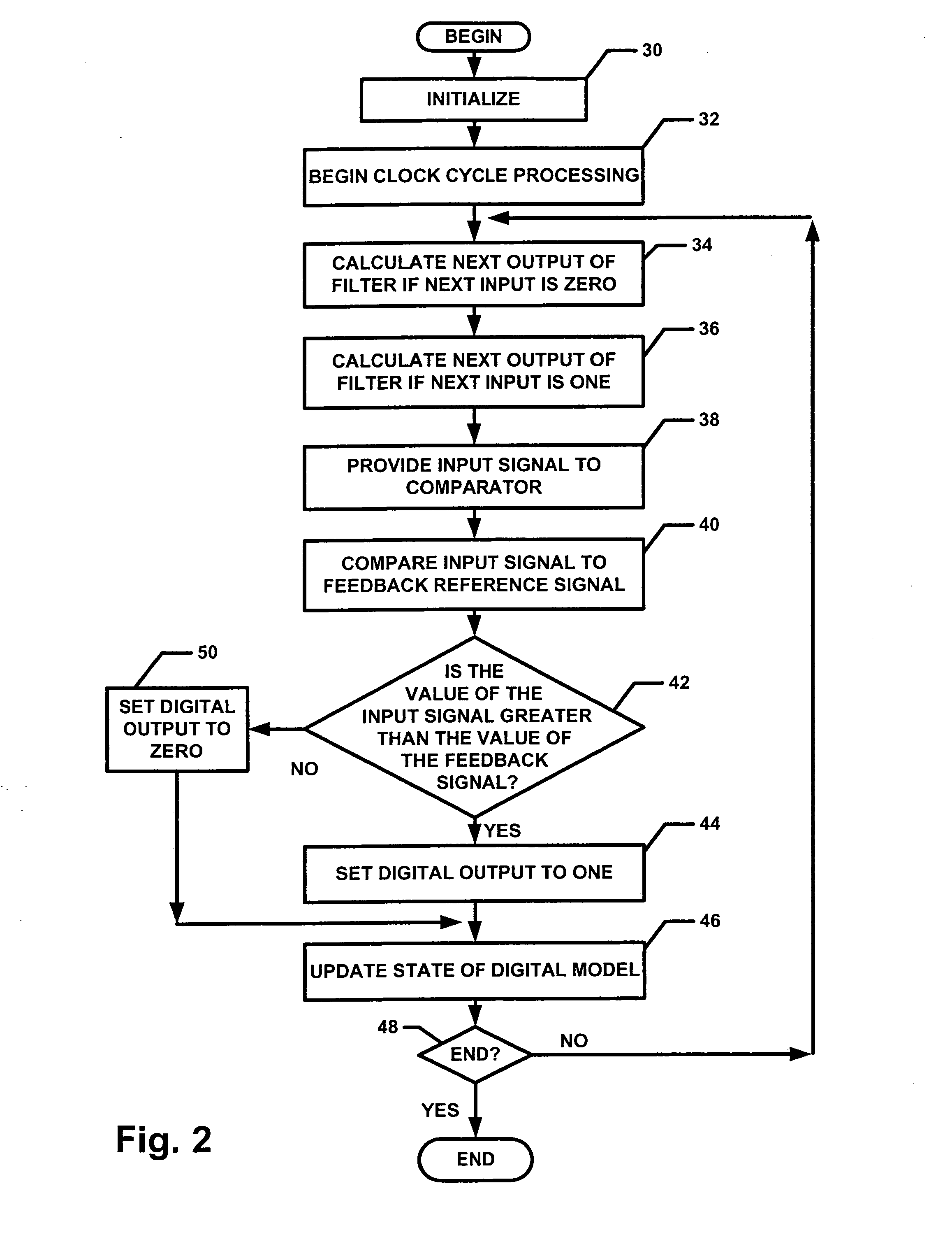
A digital to analog converter includes a digital processor having an input port adapted to receive an input signal and an output port coupled to an input port of an analog filter wherein the digital processor includes a digital feedback loop which compares a reference digital voltage with a digital voltage provided by a digital model of the analog filter. Using a completely digital feedback loop which compares an input digital voltage with the digital voltage from the digital model of the analog filter results in a single bit digital to analog converter having improved accuracy for a given clock rate and filter. The next digital state of the converter (i.e. ‘0’ or ‘1’) is selected based upon a comparison of the input (or reference) voltage with the digital voltage provided by the digital feedback loop. The digital converter output is then fed to the analog filter. If the analog filter matches the digital model, then the analog voltage will match the digital voltage, and therefore the reference voltage.

Description

CROSS-REFERENCE TO RELATED APPLICATIONS[0001]Not applicable.STATEMENTS REGARDING FEDERALLY SPONSORED RESEARCH[0002]Not applicable.FIELD OF THE INVENTION[0003]This invention relates generally to radar systems and more particularly to techniques for generating an analog waveform to modulate a radio frequency (RF) signal for use in radar systems.BACKGROUND OF THE INVENTION[0004]As is known in the art, radar systems often utilize a radio frequency (RF) signal modulated by an analog waveform. Although it is desirable to provide relatively accurate analog waveforms, it is also sometimes desirable to provide low cost systems. Thus, in such relatively low cost systems, single bit conversion is typically used to generate a desired analog waveform.[0005]As is also known, conventional single bit converters typically use Pulse Width Modulation (PWM) or Delta Sigma Modulation (DSM). PWM converters generate pulses at a fixed frequency. The pulses have a pulse width which is proportional to the de...

Claims


Application Information

Patent Timeline
IPC IPC(8): H03M1/66
CPCH03M1/0626H03M1/822
Inventor GILBERT, MICHAEL J.
Owner VALEO RADAR SYST
Learn More