Cooling fan with electric motor

a technology of cooling fan and electric motor, which is applied in the direction of liquid fuel engines, magnetic circuit rotating parts, magnetic circuit shape/form/construction, etc., can solve the problems of reducing the lifetime of the electric motor or a total failure the heat cannot be removed via the external surfaces the cooling air flow generated cannot be fully accepted, so as to improve the cooling of the electric motor, increase the thermal robustness, and reduce the effort involved in construction and installation.

Inactive Publication Date: 2006-05-09
BROSE FAHRZEUGTEILE GMBH & CO KG HALLSTADT (DE)
View PDF4 Cites 58 Cited by
  • Summary
  • Abstract
  • Description
  • Claims
  • Application Information

AI Technical Summary

Benefits of technology

[0010]The object of the invention is to improve the cooling of an electric motor and thereby to increase the thermal robustness in relation to changing and extreme environmental conditions, as are to be encountered for example in the day-to-day use in a motor vehicle. Simultaneously the effort involved in construction, as well as manufacturing and installation, is to be reduced.

Problems solved by technology

If this requirement is not observed the result can be a reduction in the lifetime of the electric motor or a total failure of the electric motor.
The cooling air flow generated can only accept the heat energy generated by the electronics at one point over a comparatively short path past the cooling fins.
Thus practically no heat can be removed via the external surfaces of the electric motor.
These design features make effective removal of heat losses more difficult In addition the arrangement of the electronics requires an additional housing cover which encloses the mounting chamber.
A additional heat removal on the outside of the motor housing cannot be undertaken here either in any of the embodiments since the cooling air flow only passes over the components generating the individual heat once.

Method used


Image

  • Cooling fan with electric motor
  • Cooling fan with electric motor
  • Cooling fan with electric motor

Examples


Embodiment Construction

[0040]Within the figures the same reference symbols are used to indicate parts with the same name and the same function.

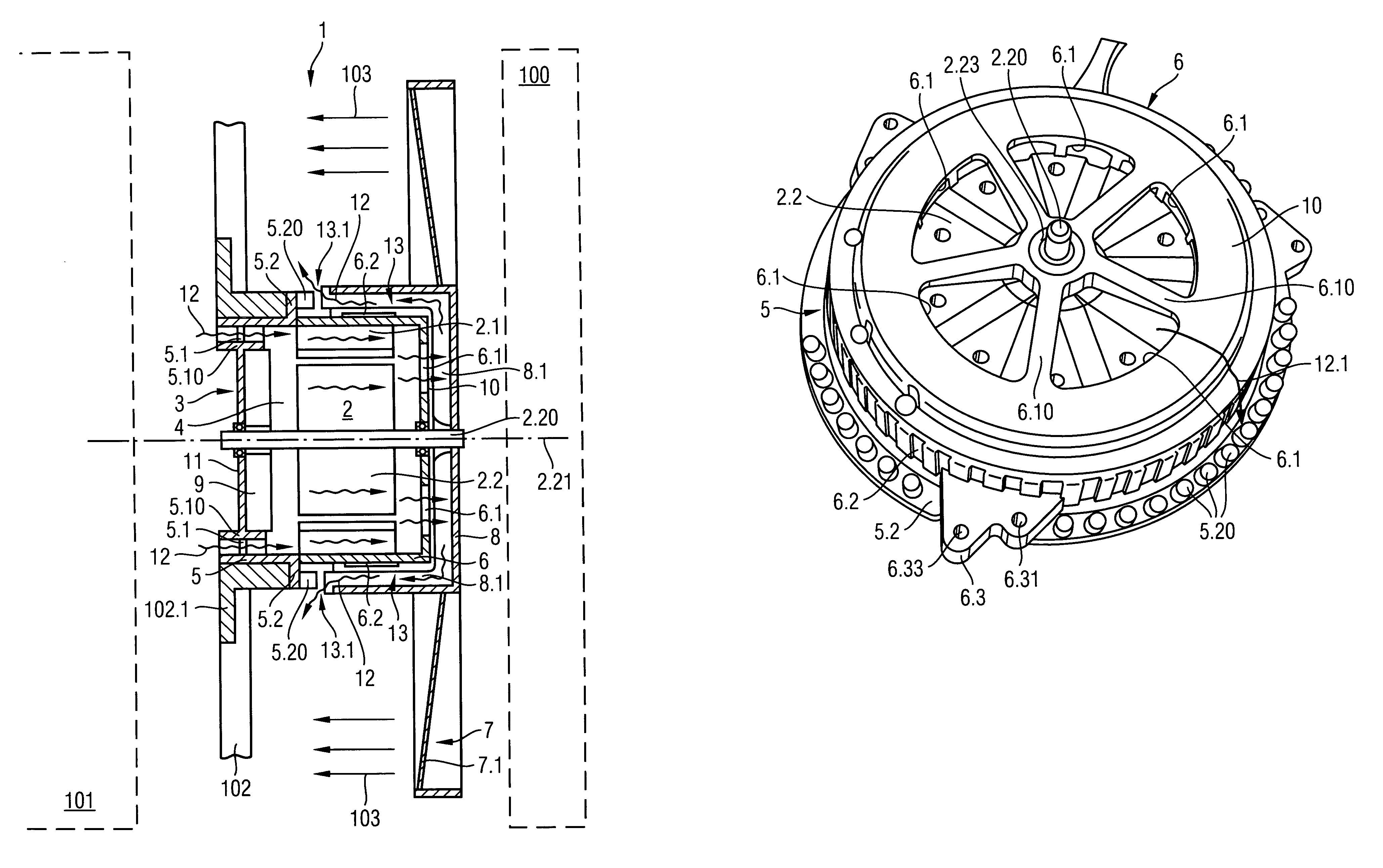
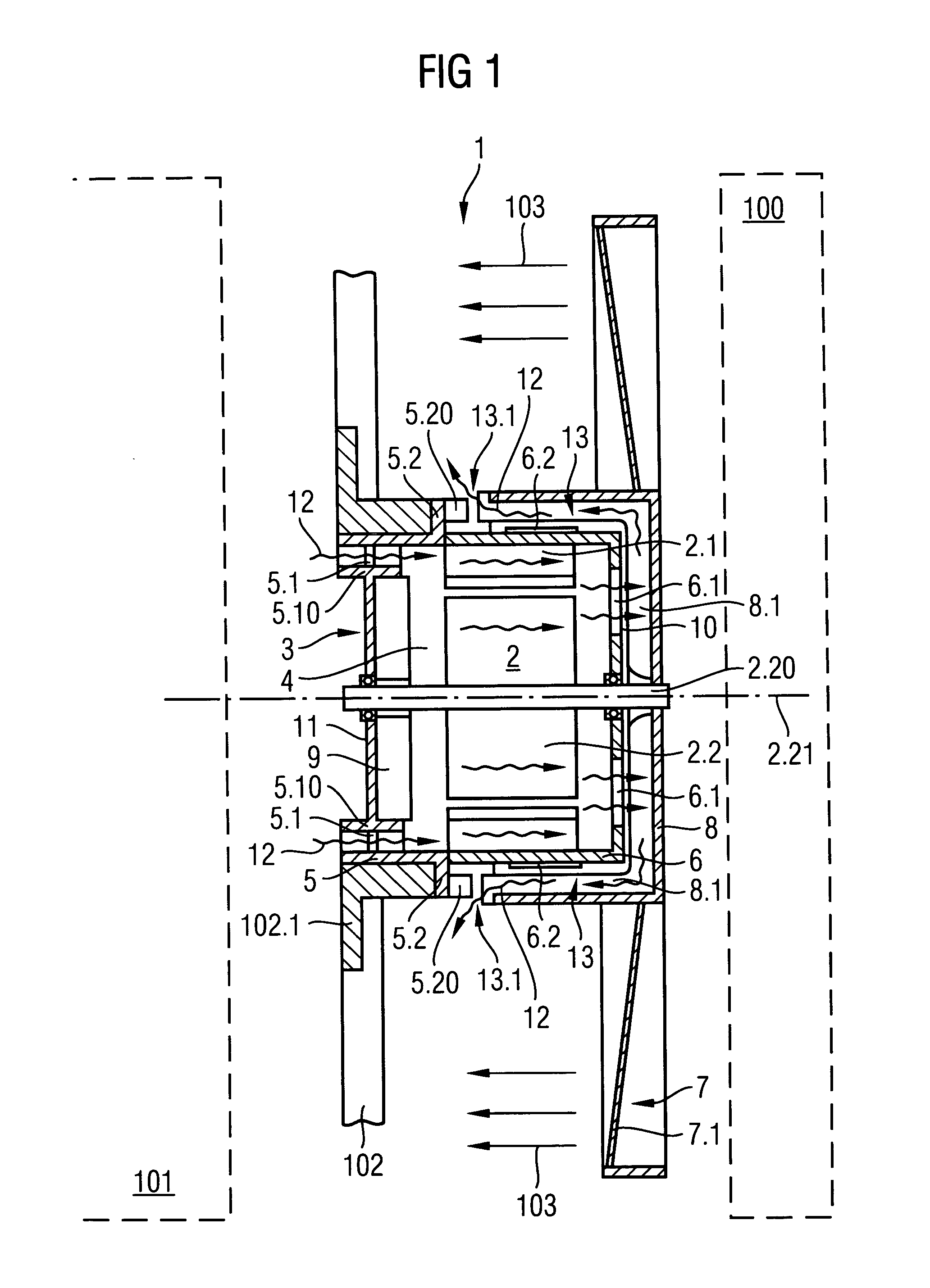
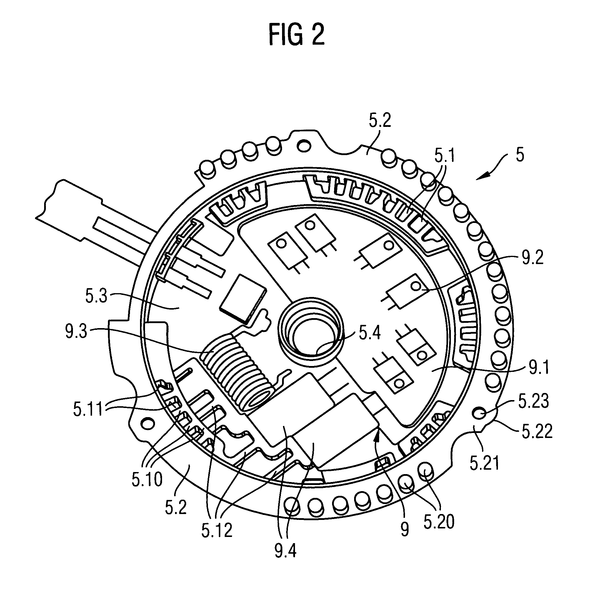
[0041]FIG. 1 shows an exemplary embodiment of a cooling fan, as is used in a motor vehicle for example, as a greatly simplified schematic diagram. This diagram shows a cooling fan arranged between a heat exchanger 100 indicated by a broken line, and an internal combustion engine 101 indicated in the same manner. As its drive, the cooling fan 1 features an electric motor 2 with a stator 2.1 and a rotor 2.2 which are surrounded by a motor housing 3. The motor housing 3 enclosing the interior of the motor housing 4 essentially consists of a rear motor housing part 5 with integrated electronics module 9 and of a front power take-off motor housing part 6 connected to the rear motor housing part 5. All parts of the motor housing are made of cast aluminum in this case. The motor housing 3 is held in a fan frame 102 which is used for installing the cooling fan 1 in the eng...


PUM


Abstract

The invention relates to a cooling fan for use in a motor vehicle. To achieve improved cooling of an electric motor it is proposed that the motor housing enclosing the electric motor be used as a heat sink for emitting waste heat into a cooling air flow. The cooling air flow for cooling the electric motor is routed here through the interior of the motor housing and subsequently along the outside of the motor housing over cooling elements in the areas of the air inlet openings and in the area or an air exit gap between fan wheel hub and front part of the motor housing. The cooling air flow is created in this case by the fan wheel hub of the fan wheel driven by the electric motor.

Description

BACKGROUND OF THE INVENTION[0001]The invention relates to a cooling fan with an electric motor drive, especially for use as a cooling fan in a motor vehicle.[0002]The cooling fan is taken to mean the fan system which essentially consists of the fan wheel with fan wheel hub and fan blades and an electric motor to drive the fan. Usually this type of cooling fan is mounted for example in a frame provided for the purpose which is fixed in the engine compartment of a motor vehicle or such like.[0003]For safe operation of electric motors it is necessary for the components and materials used not to become overheated under specific operating conditions. It is therefore necessary to ensure that no overheating occurs during the operation of the electric motor with maximum power dissipation. If this requirement is not observed the result can be a reduction in the lifetime of the electric motor or a total failure of the electric motor. The cooling of the electric motor, that is the removal of t...

Claims


Application Information

Patent Timeline
Patent Type & Authority Patents(United States)
IPC IPC(8): H02K11/00
CPCF04D25/082H02K9/06F04D29/329F04D29/5806
Inventor DE FILIPPIS, PIETROEGERLAND, MARKUSKEMMER, DETLEFMCLENNAN, PAUL STEPHENREDELBERGER, HARALD
Owner BROSE FAHRZEUGTEILE GMBH & CO KG HALLSTADT (DE)
Why Eureka
Try Eureka