
Dielectric mono-block triple-mode microwave delay filter

a microwave delay filter and dielectric monoblock technology, applied in the direction of waveguide type devices, resonators, basic electric elements, etc., can solve the problems of large cost percentage of the entire filter assembly, the inability to reduce the size of the metal housing beyond, and the current size and cost of the metal filter too large and expensiv

Inactive Publication Date: 2006-05-09
RADIO FREQUENCY SYST
View PDF39 Cites 53 Cited by
  • Summary
  • Abstract
  • Description
  • Claims
  • Application Information

AI Technical Summary

Benefits of technology

[0008]In a preferred embodiment, the invention is a method and apparatus of providing a very flat group delay over a wide frequency range.

Problems solved by technology

Because of the required volume for each resonator, the metallic housing cannot be reduced in size beyond current technology, typically 3–10 cubic inches / resonator, depending on the operating frequency and the maximum insertion loss.
Furthermore, the metallic housing represents a major cost percentage of the entire filter assembly.
Consequently, current metallic filters are too large and too costly.
Further, personal communication systems demand highly linearized microwave power amplifiers for base station applications.
However, the related art has various problems and disadvantages.
For example, but not by way of limitation, because of the required volume for the delay line / filter for the new generation communication systems, the coaxial line and metallic housing filter cannot be further reduced in size limited by maximum insertion loss.

Method used


Image

  • Dielectric mono-block triple-mode microwave delay filter
  • Dielectric mono-block triple-mode microwave delay filter
  • Dielectric mono-block triple-mode microwave delay filter

Examples


second embodiment

[0062]In a second embodiment, the circuit board supporting the filter assembly 110 is an integral part of the circuit board that is formed by other parts of the transmit and / or receive system, such as the antenna, amplifier, or analog to digital converter. As an example, FIG. 13 shows the filter assembly 110 on the same board as a 4-element microstrip-patch antenna array 150. The mono-block filter 10, 12 and combline (or premask) filter 120 are mounted to the same board that supports a 4-element antenna array 150. The mono-block 10 and mask filters 120 are on one side of the circuit board. The low pass filter 130 and the antenna 150 are on the opposite side. A housing could be included, as needed.

third embodiment

[0063]In a third embodiment, the filter assembly 110 is contained in a box and connectors are provided either as coaxial connectors or as pads that can be soldered to another circuit board in a standard soldering operation. FIG. 14 shows two examples of packages with pads 160. The filter package can include cooling fins if required. A package of the type shown in FIG. 14 may contain only the mono-block 10, 12, as shown, or it may contain a filter assembly 110 of the type shown in FIG. 13. FIG. 14(a) shows the mono-block filter 10, 12 packaged in a box with the internal features highlighted in FIG. 14(b). The pads 160 on the bottom of the box in FIG. 14(a) would be soldered to a circuit board. FIG. 14(c) shows a similar package for a duplexer consisting of two filters with one common port and, therefore, three connecting pads 160. A package of the type shown here may contain only the mono-block 10, 12 or it may contain a filter assembly 110.

[0064]Preselect or Mask Filter: Common to a...


PUM


Abstract

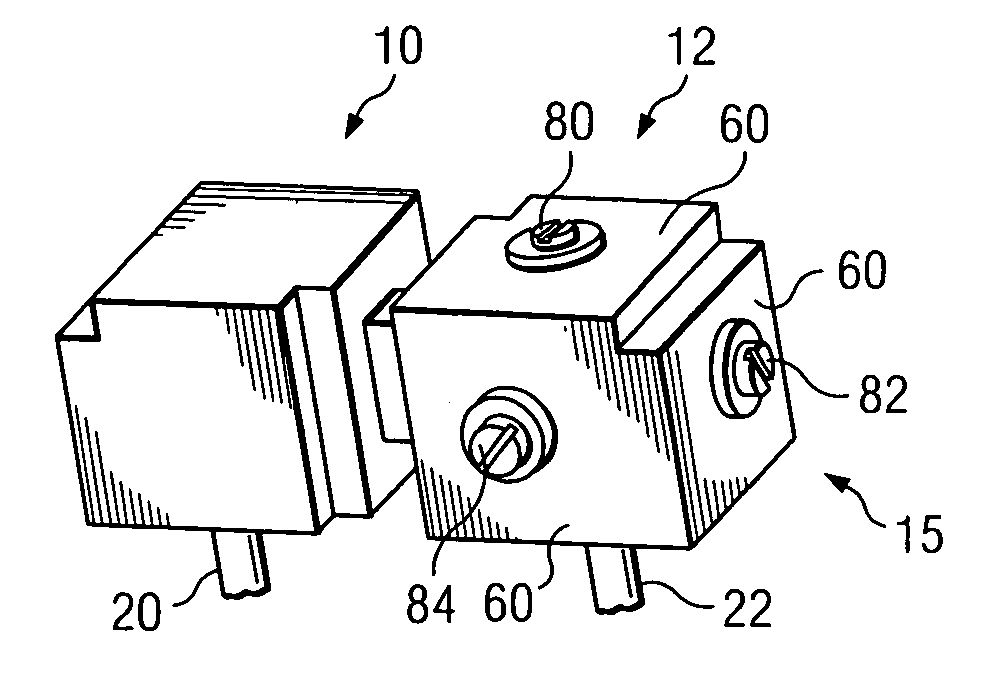
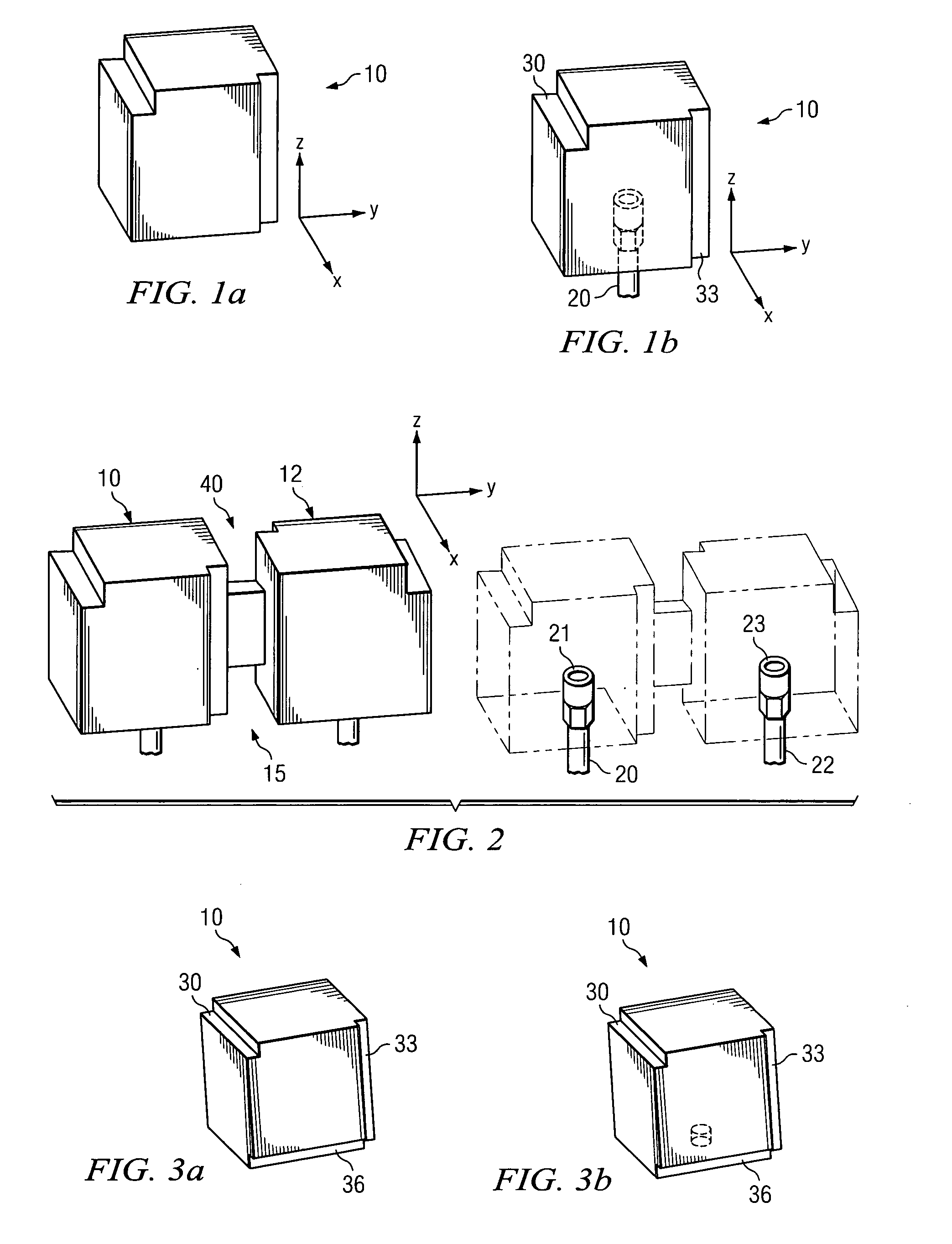
A delay filter uses the dielectric mono-block triple-mode resonator and unique inter-resonator coupling structure, having smaller volume and higher power handling capacity. The triple-mode mono-block resonator has three resonators in one block. An input / output probe is connected to each metal plated dielectric block to transmit microwave signals. Corner cuts couple a mode oriented in one direction to a mode oriented in a second, mutually orthogonal direction. An aperture between two blocks couples all six resonant modes, and generates two inductive couplings by magnetic fields between two modes, and one capacitive coupling by electric fields. The input / output probes, coupling corner cuts and aperture are aligned such that all six resonators are coupled in the desired value and sign, so constant delay on the transmitted signal within certain bandwidth can be achieved. By connecting the input and output probes to the base printed circuit board, the delay filter is surface mountable.

Description

[0001]This is a continuation-in-part application of application Ser. No. 09 / 987,353 filed Nov. 14, 2001, the disclosure of which is incorporated herein by reference.BACKGROUND OF THE INVENTION[0002]1. Field of the Invention[0003]This invention relates to filter assemblies. More particularly, this invention discloses triple-mode, mono-block resonators that are smaller and less costly than comparable metallic combline resonators, including a microwave flat delay filter.[0004]2. Background of the Invention[0005]When generating signals in communication systems, combline filters are used to reject unwanted signals. Current combline filter structures consist of a series of metallic resonators dispersed in a metallic housing. Because of the required volume for each resonator, the metallic housing cannot be reduced in size beyond current technology, typically 3–10 cubic inches / resonator, depending on the operating frequency and the maximum insertion loss. Furthermore, the metallic housing r...

Claims


Application Information

Patent Timeline
IPC IPC(8): H01P1/20H01P1/208H01P7/10H01P7/00H01P7/06H01P11/00
CPCH01P11/007H01P1/2086H01P7/00
Inventor WANG, CHIWANG, WEILIWILBER, WILLIAM D.BLAIR, WILLIAM D.
Owner RADIO FREQUENCY SYST
Learn More