Method for presenting fisheye-camera images

Inactive Publication Date: 2006-05-09
APPRO TECH
View PDF10 Cites 9 Cited by
  • Summary
  • Abstract
  • Description
  • Claims
  • Application Information

AI Technical Summary

Benefits of technology

[0018]The method disclosed by the invention is not only simple but also low-cost because the required optical parameters have been ensured after the paramete

Problems solved by technology

These applications, however, currently have a common limitation of narrow visual angles and insufficient depth of field.
Technologies developed for the usual visual disciplines resulted in no capability to process the images of the FIS.
However, the catadioptric systems often elongate the ray traces, complicate the image-forming mechanism and attenuate the imaging signals due to indirectly taking the reflective images through the added optical elements.
A blind area will be unavoidable at the center of an image because of the front installation of the reflective element.
However, the first method of a rotation type cannot take a whole scene at the same time so that a drawback of asynchronism remains.
In addition to the extra cost of multi-cameras, the sampling and integration of the images from individual cameras still present many further problems.
Major parts of the mentioned image-based postulates, however, are unrealistic because many essential factors or variations have not been taken into consideration.
A third factor concerns the errors caused in locating the image border.
The radial decay of the radiometric response is an unavoidable phenomenon in a lens, especi

Method used


Image

  • Method for presenting fisheye-camera images
  • Method for presenting fisheye-camera images
  • Method for presenting fisheye-camera images

Examples


Embodiment Construction

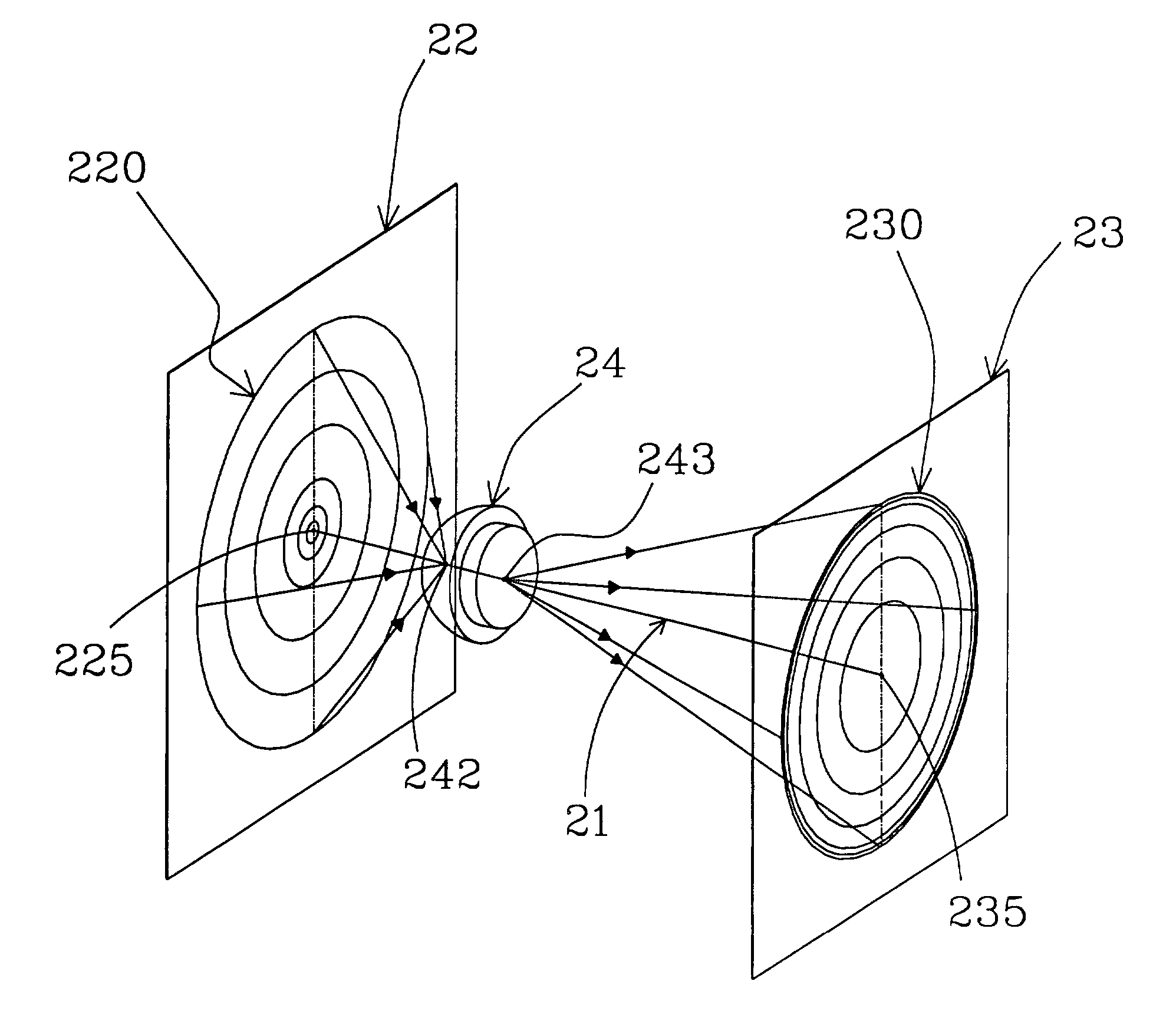
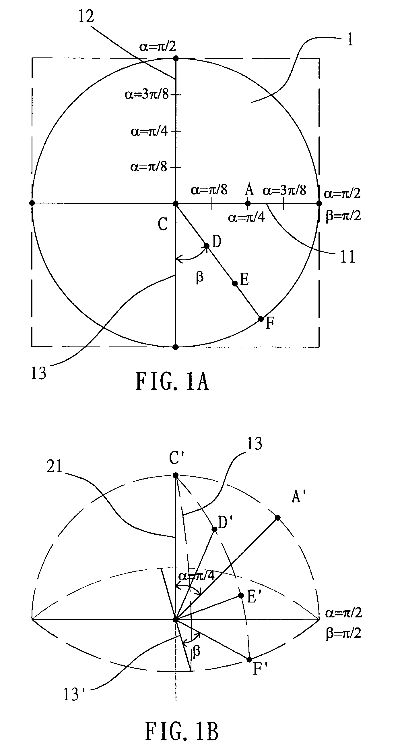
[0035]The fisheye-camera image is possessed of a severe barrel deformation comparing with the distortions by a normal camera. The distortion is center-symmetric on the image plane and axis-symmetric in the projecting space. This phenomenon is well known to those skilled in the related art. However, the incident rays from subjects will logically converge onto a unique spatial optical center, and then divergently image on the image plane.

[0036]Considering the geometrical condition, a symmetric image can be obtained by a planar drawing capable of representing a spatial-symmetric geometrical arrangement. Therefore, the optical axis and the principal point are determinable when the symmetric image has been absolutely referred to by means of adjusting the test fisheye camera (also termed as the fisheye image sensor, simplified as the FIS hereinafter). The obtained object-to-image scale data is subsequently based to locate the spatial optical center (also termed viewpoint, simplified as VP...


PUM


Abstract

The present invention is a method for presenting the fisheye-camera images. A calibration target with a concentric-and-symmetric pattern (PCT) is utilized to assist in parameterizing a fisheye camera (FIS) in order to ascertain the optical parameters comprising the principal point, the focal length constant and the projection function of the FIS. Hence, the position of an imaged point referring to the principal point on the image plane directly reflects its corresponding zenithal distance α and azimuthal distance β of the sight ray in space so as to normalize the imaged point onto a small sphere. Further according to the map projections in cartography capable of transforming the global geometry into flap maps, the interesting area in a field of view can be accordingly transformed by a proper projection method. The image transforming method disclosed in the invention is simple, low-cost, suitable to various FISs with different projection mechanisms and capable of transforming the fisheye-camera images for particular functions, such as the approach of normal human visual perception, video data encryption, and image compression/transformation with a high fidelity.

Description

BACKGROUND OF THE INVENTION[0001]1. Field of Invention[0002]The invention relates to a method for presenting fisheye-camera images, and in particular to a method integrating the multicollimator metrology and cartography in order to systematically describe the projection mechanism of the fisheye camera and to transform the fisheye-camera images into ones suitable for advanced visual applications.[0003]2. Related Art[0004]The camera systems in the field of artificial vision preferred using lenses with a narrow field of view (FOV) in order to obtain images approaching an ideal perspective projection mechanism for precise measurement. The perspective projection is usually a basis to deduce the camera's parameters while modeling the barrel distortion with a polynomial in the variable of the image's dimensions. The obtained intrinsic and extrinsic parameters can be employed to the visual applications in the quest for better precision, such as 3-D cubical inference, stereoscopy, automatic ...

Claims


Application Information

Patent Timeline
IPC IPC(8): H04N5/225G02B13/06G06T3/00H04N7/18H04N17/00
CPCG02B13/06G06T3/0018H04N7/183H04N5/23238H04N17/002H04N23/698
Inventor JAN, GWO-JENCHANG, CHUANG-JAN
Owner APPRO TECH
Why Eureka
Try Eureka