Image-rejection mixer having high linearity and high gain

a mixer and linear technology, applied in the direction of oscillator generators, transmission noise suppression, electrical apparatus, etc., can solve the problems of limiting the maximum achievable value, limiting the available headroom to the output stage, and difficult to achieve, so as to achieve high conversion gain, high linearity, and high gain

Active Publication Date: 2006-05-09
MAXIM INTEGRATED PROD INC
View PDF6 Cites 19 Cited by
  • Summary
  • Abstract
  • Description
  • Claims
  • Application Information

AI Technical Summary

Benefits of technology

[0010]An integrated semiconductor image-rejection mixer having high linearity and high gain is disclosed. In addition to the components of a classic image-rejection architecture, the present mixer has a high-frequency current-diverting stage that permits the operation of the output stage with high conversion gain and sufficient headroom for good linearity, even in cases where the supply voltage is relatively low (such as 3 V). The conversion gain of the mixer and its image-rejection performance can be changed by changing the load resistances and the elements of the output polyphase network, with minor effects on linearity and no change in power consumption or DC levels. The power consumption of the image-rejection mixer is low because no additional DC current is required for buffers or amplifier stages.

Problems solved by technology

This is difficult however, because of the sharp and variable frequency filters required.
First of all, if high linearity (high third-order input-referred intermodulation point, or IIP3) is desired for the imager-ejection mixer, then degeneration must be used in the RF stage as shown, and that will limit the available headroom to the output stage (thus limiting the maximum achievable value for IIP3).
The degeneration in the RF stage also reduces the conversion gain of the mixer.
More importantly, however, because the output polyphase network and the load resistors are in the DC current path of the output stage, the output headroom is severely reduced especially in the case of low-voltage circuits with multiple-section polyphase networks, thereby reducing the linearity of the mixer.
Restoring the conversion gain is possible using additional gain stages at the output, with the drawback of having to use more supply current.
The drawback of this approach is that more supply current is needed for the buffers, especially for minimizing the linearity (IIP3) degradation that occurs at the buffer / polyphase network interface.

Method used


Image

  • Image-rejection mixer having high linearity and high gain
  • Image-rejection mixer having high linearity and high gain
  • Image-rejection mixer having high linearity and high gain

Examples


Embodiment Construction

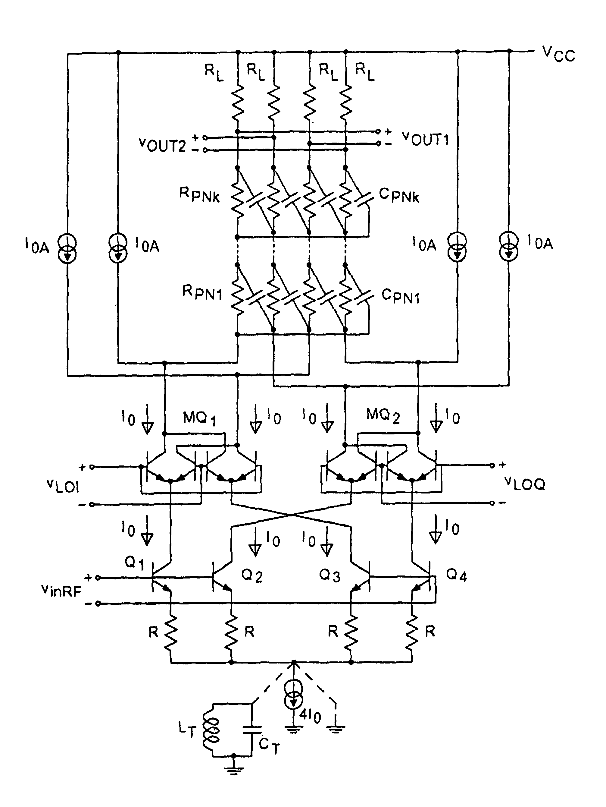
[0021]In the description to follow, references may be made to local oscillator signals, or inphase and quadrature local oscillator signals, such as LOI, and LOQ shown in the various Figures to be described herein. It is to be understood that such references are for purposes of convenience and not for purposes of limitation, as such local oscillator signals, by way of example, may be derived from an oscillator accompanying the image-rejection mixer, or may be made available locally from a remote source, such as over a wire connection or a wireless connection, or may even be recovered from the RF signal itself, all as is well known in the art. The source of the local oscillator signal is dependent on the application of the present invention, not the invention itself, and is simply to be distinguished from the RF signal itself.

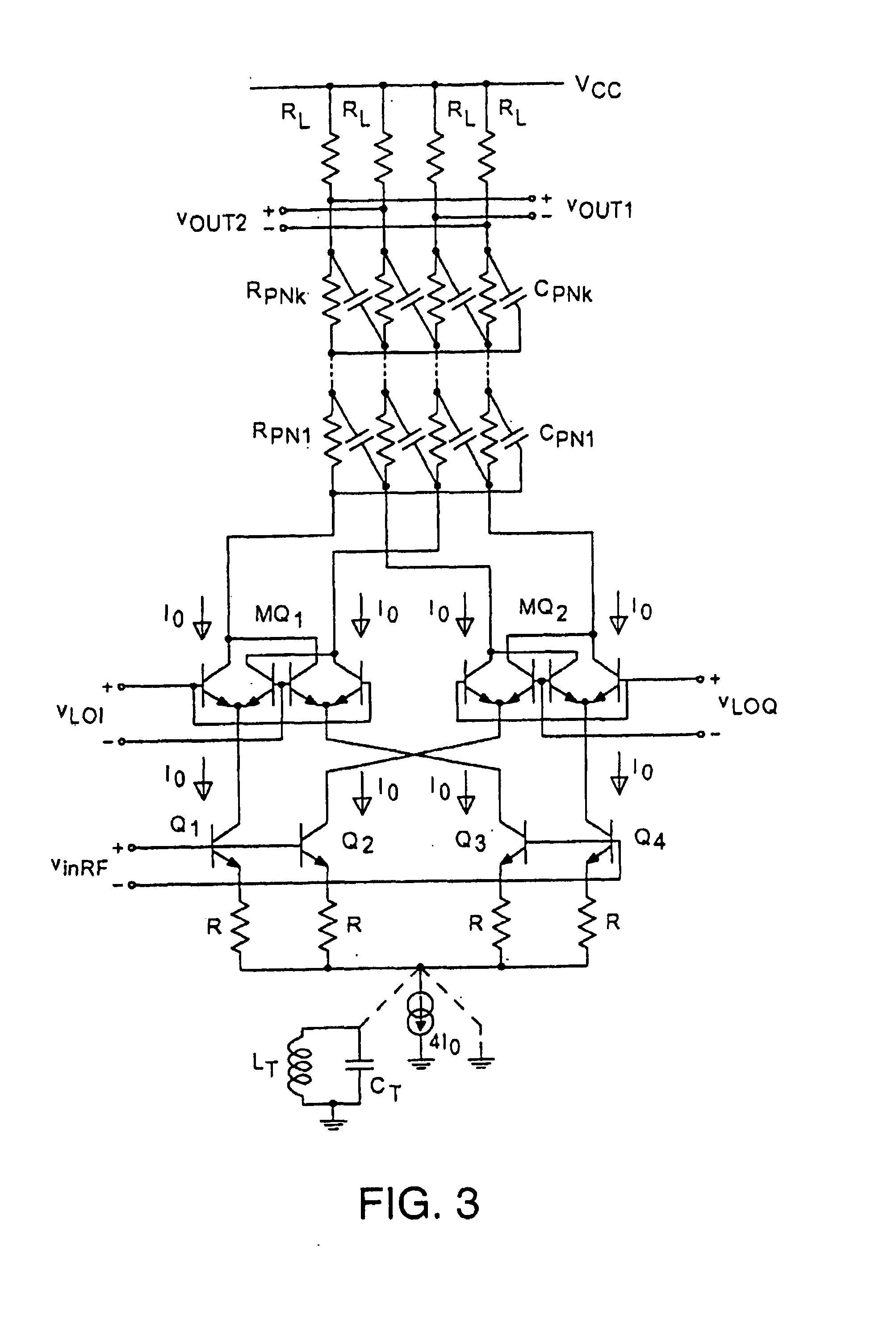
[0022]A first embodiment of the image-rejection mixer in accordance with the present invention is shown in FIG. 5. In this embodiment, the mixing cells (Gilbert ...


PUM


Abstract

An integrated semiconductor image-rejection mixer having high linearity and high gain. In addition to the components of a classic image-rejection architecture, the present mixer has a high-frequency current-diverting stage that permits the operation of the output stage with high conversion gain and sufficient headroom for good linearity, even in cases where the supply voltage is relatively low (such as 3 V). The conversion gain of the mixer and its image-rejection performance can be changed by changing the load resistances and the elements of the output polyphase network, with minor effects on linearity and no change in power consumption or DC levels. The power consumption of the image-rejection mixer is low because no additional DC current is required for buffers or amplifier stages.

Description

BACKGROUND OF THE INVENTION[0001]1. Field of the Invention[0002]The present invention relates to the field of imager-ejection mixers.[0003]2. Prior Art[0004]When an RF (radio frequency) signal comprising a plurality of channels of information on different frequencies is down shifted to downshift the desired channel to a predetermined IF (intermediate frequency) frequency (actually a frequency range), one or more other channels may be downshifted to fall into the same IF frequency range. In particular, consider an RF frequency band being downshifted by mixing with another frequency fLO. The mixing will provide sum and difference frequencies. For downshifting, the sum frequencies will be well above any frequency range of interest and easily filtered out of the resulting signal. For the difference frequencies however, when one or more channels in the RF signal are downshifted to the IF frequency range fIF, one or more other channels in the RF signal that are 2fIF away from the channels...

Claims


Application Information

Patent Timeline
Patent Type & Authority Patents(United States)
IPC IPC(8): H04B1/10
CPCH03D7/1425H03D7/1433H03D7/165H03D7/1458H03D2200/0088H03D2200/0025
Inventor CIUBOTARU, ALEXANDRU A.
Owner MAXIM INTEGRATED PROD INC
Why Eureka
Try Eureka