
Therapeutic cellular stent

Inactive Publication Date: 2006-05-16
SPIELBERG THEODORE E
View PDF12 Cites 50 Cited by
  • Summary
  • Abstract
  • Description
  • Claims
  • Application Information

AI Technical Summary

Benefits of technology

[0013]Yet another aspect of the invention is to efficiently provide stem cells or autologous bone marrow cells directly to areas of organ injury, to thereby facilitate repair of the injured organ.
[0016]The stent of the present invention provides significant flexibility in the selection of the site of implant of the cells. For example, in the case of a lesion in a vessel that must be treated, one may implant the stent at the site of the lesion, the stent in this case incorporating mast cells that enhance the secretion of heparin at the site, or stem cells or other forms of therapeutic cells where such cells have been lost due to injury. In other cases, one may choose to implant the stent (and the cells within it) at any convenient site in the body for systemic transport of cell products over a broader area or alternatively to service a particular organ. Moreover, the stent may be constructed of a biodegradable substance such as catgut or a polymer so that it disappears, leaving the transplanted cells enclosed within the blood vessel wall.

Problems solved by technology

In the liver, the sinusoids provide blood, but the cells may obstruct these sinusoids, thus inducing portal hypertension and even cirrhosis of the liver.
Other sites have been tried (e.g., the renal capsule); however, the lack of immediate vascular access poses problems for these approaches.
A disadvantage to such an approach is that the pores of these membranous devices can be plugged with proteinaceous deposits.
Further, the membranes also tend to increase clotting.
In each case this compromises the viability of the transplanted cells and their ability to function.
Also, vascular grafts or combination stent-grafts using Dacron or ePTFE increase thrombogenicity and compromise blood flow by increasing the inflammatory response with neointimal proliferation.

Method used


Image

  • Therapeutic cellular stent
  • Therapeutic cellular stent

Examples


Embodiment Construction

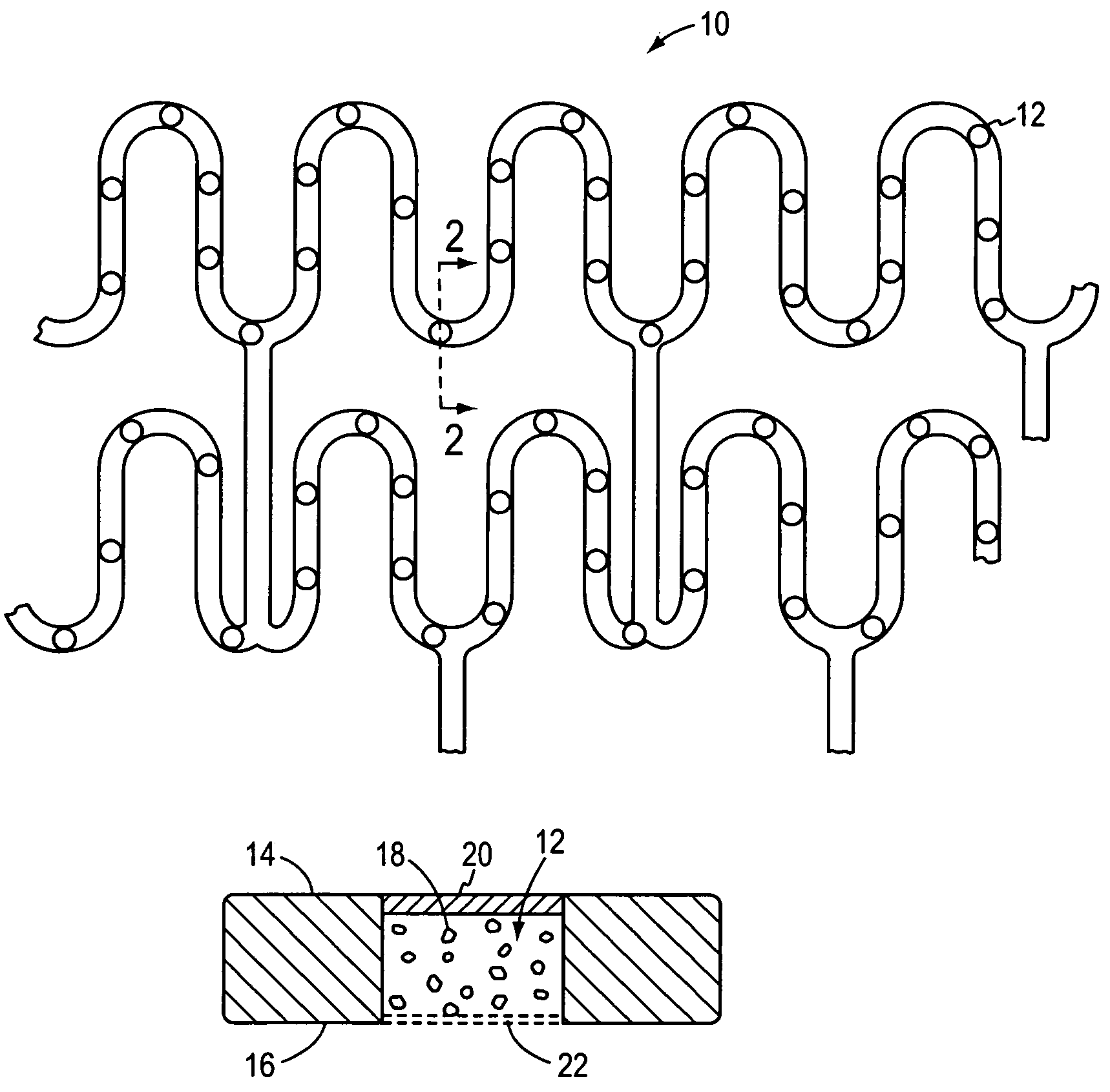
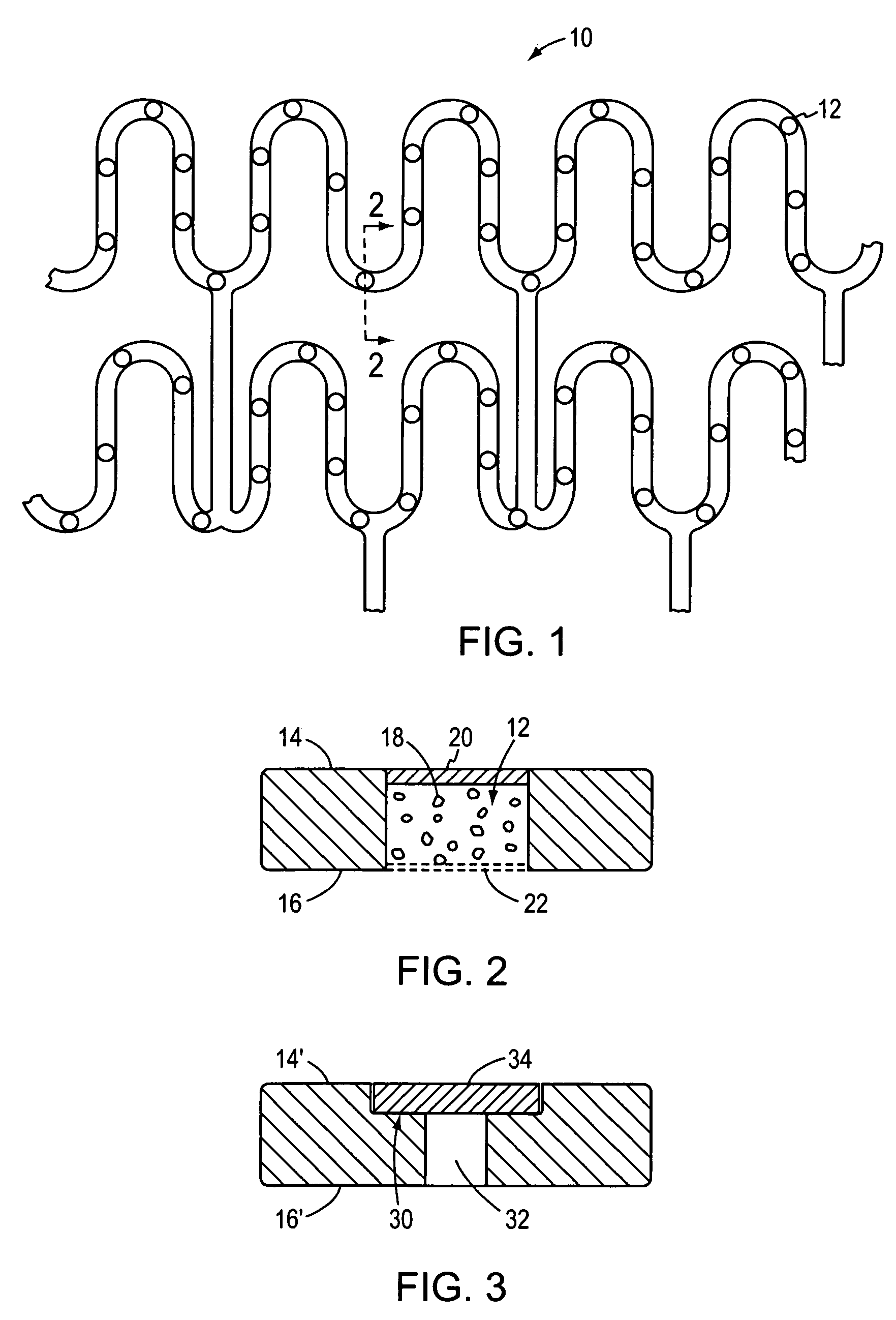
[0021]In FIGS. 1 and 2, an illustrative stent 10 that may be used in accordance with the present invention is shown in the form of a mesh whose radial cross-section is collapsible for insertion into a blood vessel and is thereafter expansible (e.g., by inflating a balloon) into contact with the inner wall of the blood vessel to thereby secure the stent at a desired location. Stents of this general type are known in the art. As modified by the present invention, however, and as shown in cross-section in FIG. 2, a plurality of wells 12 are spaced along one or more portions of the stent and extend through the stent from an upper surface 14 to a lower surface 16. The wells carry charges of living cells 18 that are confined within the well at the upper end of the cell by a thin membrane or skin 20 of biodegradable material such as albumin or other gelatinous or protinaceous material, and at the lower end of the cell by a mesh or screen 22 of sufficient porosity to admit cell nutrients in...


PUM


Abstract

A vascular stent carries living therapeutic cellular material. The stent in widely implantable over the vascular system, and allows either localized or systemic delivery of the therapeutic products produced by the cellular material to thereby enhance patient treatment.

Description

BACKGROUND OF THE INVENTION[0001]1. Field of the Invention[0002]The invention relates to vascular stents and, more particularly, comprises a vascular stent which facilitates cellular transplant in animal bodies such as humans.[0003]2. Background Information[0004]Stents are commonly used to support blood vessels whose walls have been damaged or to bridge and repair vessels that have been injured. Typically, such stents consist of an expansible mesh which is collapsible during insertion into a vessel and thereafter expansible (e.g., by means of a balloon catheter) to firmly engage the inner wall surface of a blood vessel and secure it in place.[0005]In addition to providing structural support, some stents have often been coated with various medications for such purposes as minimizing inflammation and providing treatment. Examples of commonly used stents are described in “Handbook of Coronary Stents”, 2d ed., by Patrick W. Serruys and Michael J B Kutryk, Eds. (1997, 1998). In addition,...

Claims


Application Information

Patent Timeline
IPC IPC(8): A61F2/06
CPCA61F2/91A61F2/915A61L31/005A61F2230/0013A61F2250/0068A61F2002/91533
Inventor SPIELBERG, THEODORE E.
Owner SPIELBERG THEODORE E
Learn More