Microscopic imaging apparatus and method

a confocal imaging and microscope technology, applied in the field of hand-held confocal imaging system, can solve the problem of not providing a handheld instrument readily usable by a surgeon

Inactive Publication Date: 2006-05-16
CALIBER IMAGING & DIAGNOSTICS
View PDF23 Cites 19 Cited by
  • Summary
  • Abstract
  • Description
  • Claims
  • Application Information

AI Technical Summary

Benefits of technology

[0006]It is another object of the invention to provide an improved confocal imaging system which provides images of dermatological tissues and avoids the need for biopsies to detect the location of such abnormalities as basal cell carcinomas and melanomas.
[0007]It is a still further object of the present invention to provide an improved confocal dermatological imaging system which does not require ionizing radiation and may use a laser beam.
[0008]It is a still further object of the present invention to provide an improved confocal imaging system which provides in vivo imaging of dermatological tissue both at and below the skin and which may be handheld and which is capable of operating in various scattering media.
[0009]It is a still further object of the present invention to provide an improved confocal dermatological imaging system which may use a computer to generate images from data produced by the optics which provides confocal imaging and to display or provide images for further evaluation or computer enhancement.

Problems solved by technology

Such proposals have not provided a handheld instrument which is readily usable by a surgeon in clinical examinations for imaging the epidermis and dermis, especially in vertical sections or in horizontal sections at desired depths below the surface of the skin.

Method used


Image

  • Microscopic imaging apparatus and method
  • Microscopic imaging apparatus and method
  • Microscopic imaging apparatus and method

Examples


Embodiment Construction

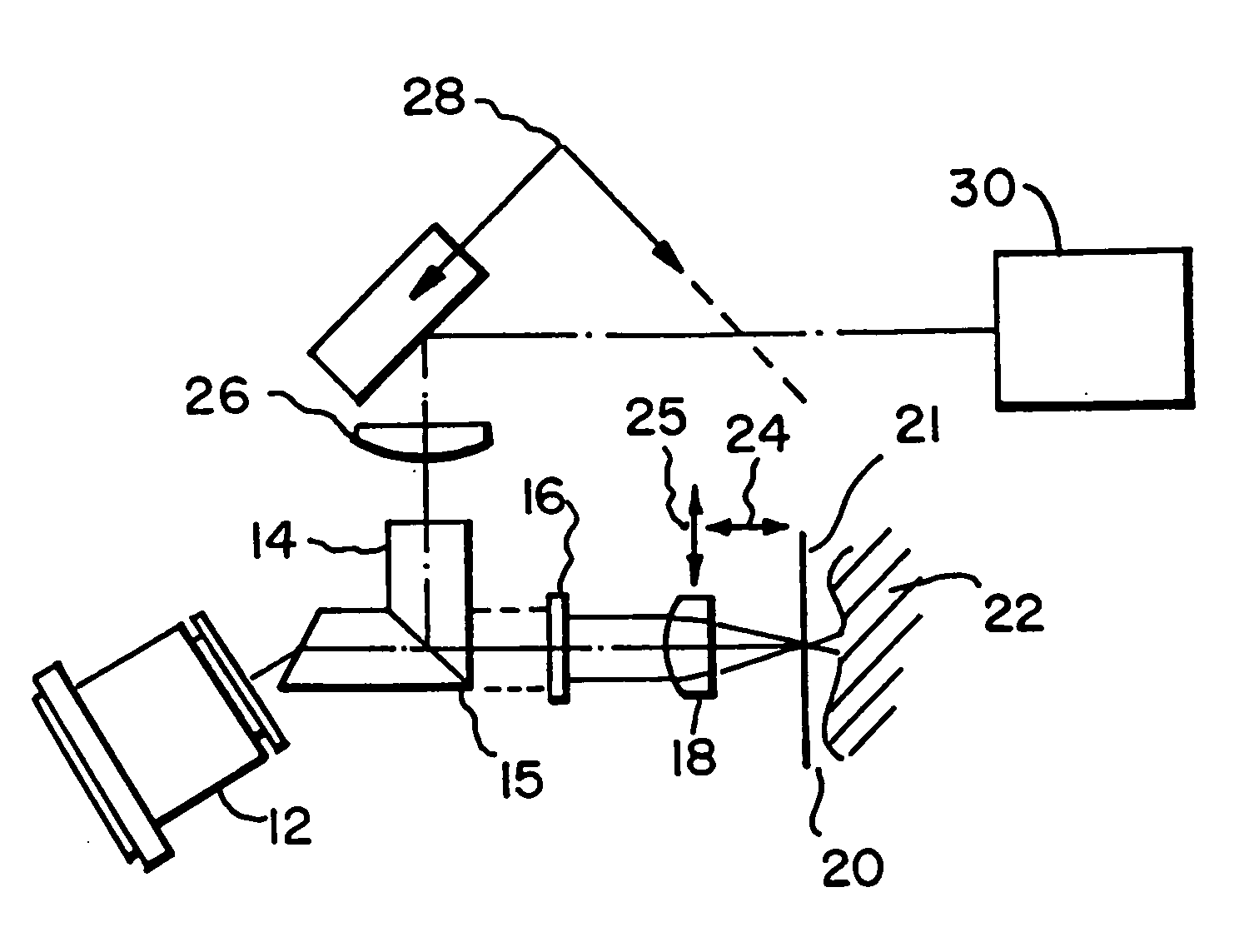
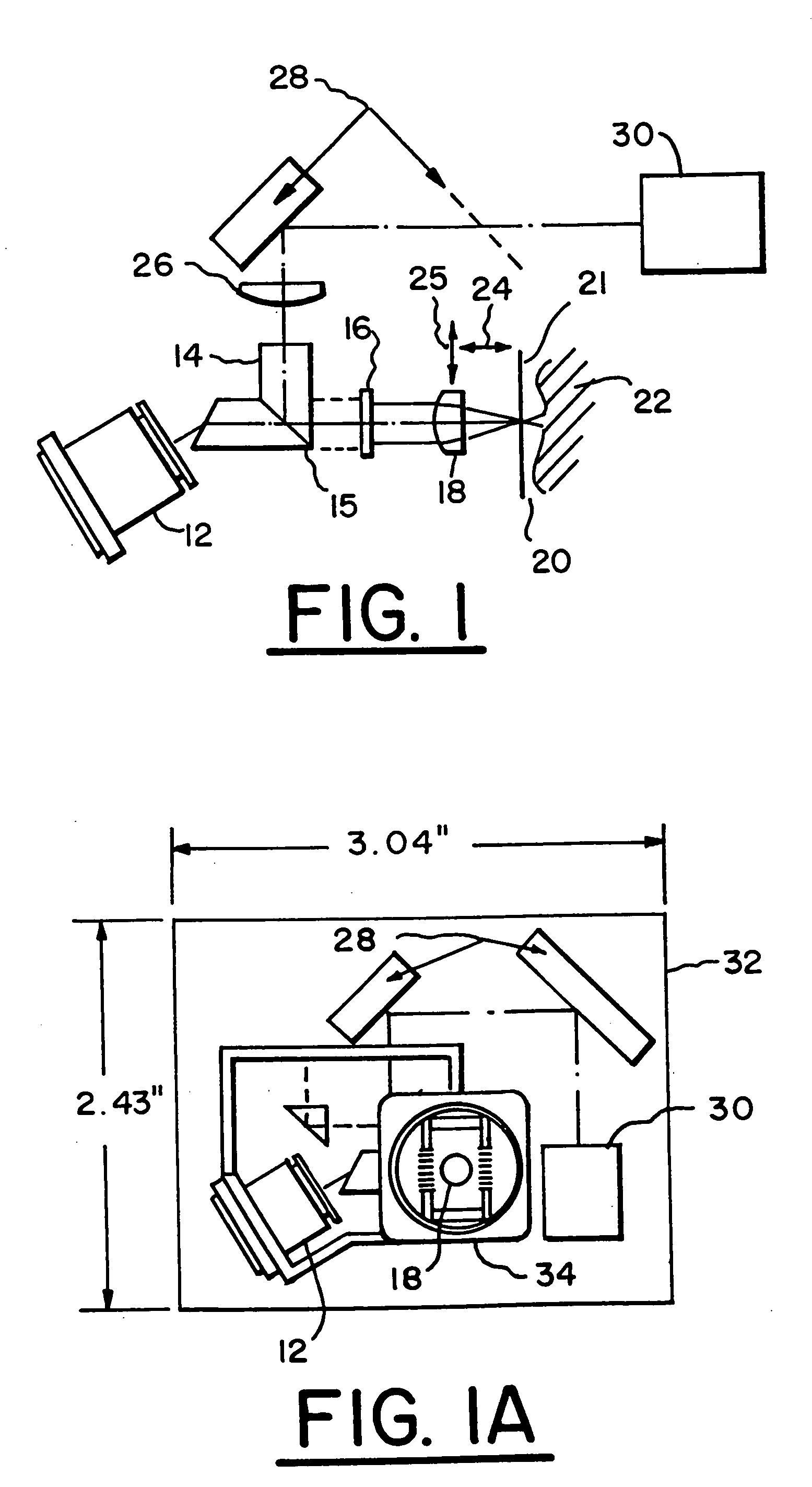
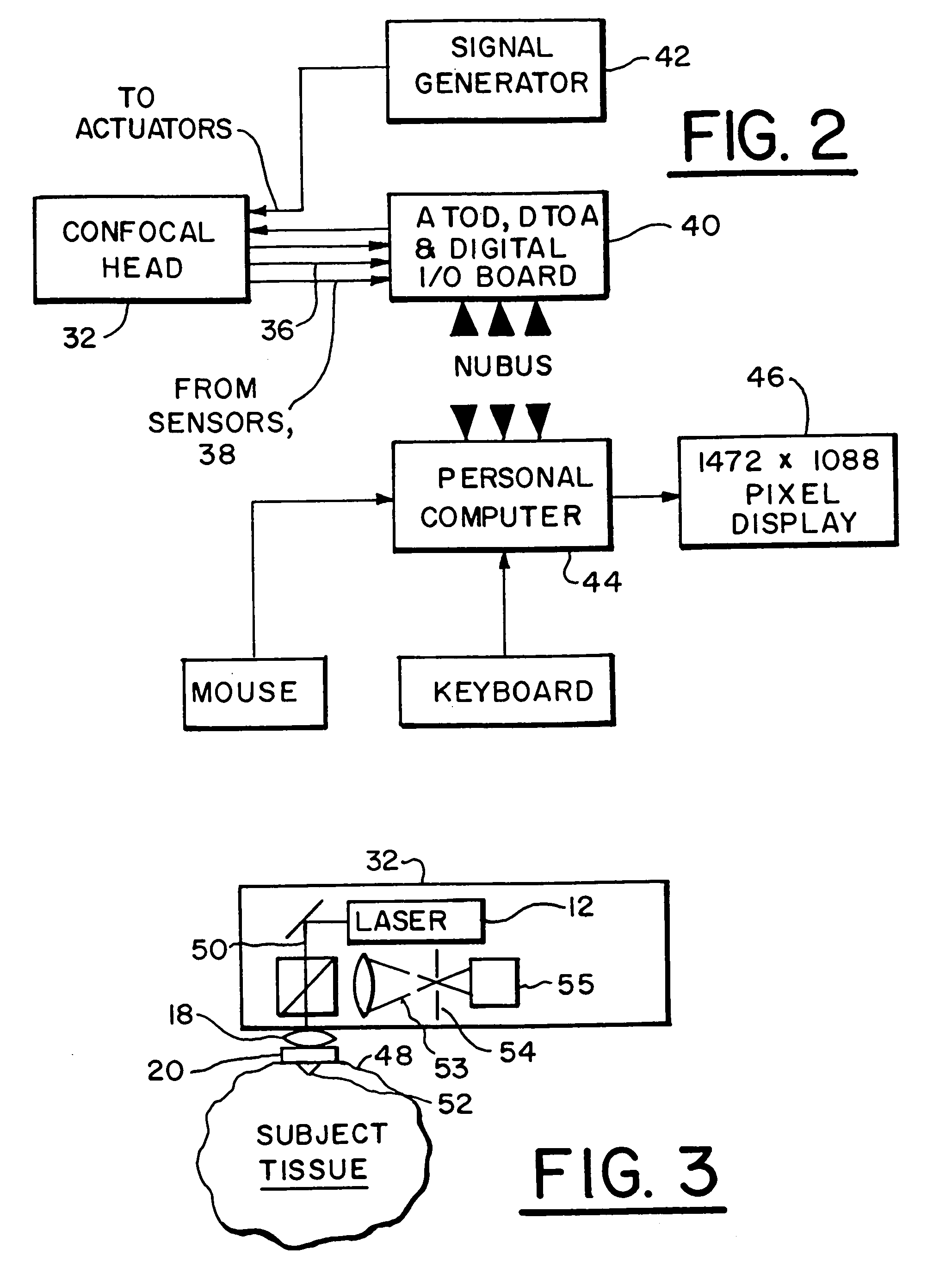
[0015]Referring to FIG. 1 there is shown a system 10 for in vivo diagnosis of dermatological tissues. The system 10 may be embodied in a handheld head 32 as shown in FIG. 1a and schematically in FIG. 3.

[0016]Referring more particularly to FIG. 1 there is shown a system 10 (or instrument) which contains optics of the type which are used in optical data storage heads which are used in recording and reading optical disks. Light from a laser diode, contained in a laser and collimator assembly 12, is collimated by a diffraction limited lens in the assembly 12 and is incident at an oblique angle on a beam splitter assembly 14. Refraction at this oblique angle causes the elliptical laser diode beam to become circular in cross-section. The circular beam passes through the beam splitter assembly 14 and a quarter wave plate 16 and is focused into the tissue 22 via a contact window 20 (a glass window plate) spaced from the sample, specimen or tissue 22 being examined, preferably by an optical ...


PUM


Abstract

An imaging apparatus is provided for imaging tissue samples substantially beneath the surface of the tissue sample. The apparatus includes an objective lens and a window defining a tissue contacting surface in pressure contacting relationship with the surface of the tissue sample when the tissue sample is imaged by the objective lens to view tissue structures for pathological applications. The objective lens focuses an illumination beam through the window to the tissue sample and receives returned reflected light of the beam representative of one or more sections of the tissue sample. The apparatus enables a method for in vivo observation of tissue for diagnosis of conditions substantially beneath the surface of the tissue sample. Both two and three-dimensional imaging may be provided for diagnosis and location of basal cell carcinomas and melanomas, and so as to enable visualization of tumor borders prior to excision.

Description

[0001]This application is a continuation of application Ser. No. 09 / 001,016 filed Dec. 30, 1997, now U.S. Pat. No. 6,263,233, which is a continuation of application Ser. No. 08 / 650,684 filed May 20, 1996, now U.S. Pat. No. 5,788,639, which claims the priority benefit of provisional application Ser. No. 60 / 001,141, filed Jul. 13, 1995.FIELD OF THE INVENTION[0002]The present invention relates to handheld confocal imaging system for in vivo clinical examinations of dermal and subdermal tissues using non-ionizing radiation, and particularly laser radiation which is of a wavelength capable of penetrating into the skin.[0003]The invention is especially suitable for providing an instrument for dermal pathology applications. The invention is also applicable for visualizing sections in other scattering media than tissue. The invention enables the use of a laser as a source of illumination. The instrument may provide data to image processing computers, which may be programmed to provide high ...

Claims


Application Information

Patent Timeline
Patent Type & Authority Patents(United States)
IPC IPC(8): A61B6/00A61B5/00A61B5/103
CPCA61B5/0059A61B5/0064A61B5/444A61B5/0068A61B2562/146
Inventor ZAVISLAN, JAMES M.EASTMAN, JAY M.
Owner CALIBER IMAGING & DIAGNOSTICS
Why Eureka
Try Eureka