Proximal coupler for optical fibers

a technology of optical fibers and couplers, applied in the field of optical waveguides, can solve the problems of affecting the performance of the proximal coupler, and inconsistent fiber packing between the couplers, so as to eliminate any damage to the optical fiber, and improve the performance of the proximal coupler.

Inactive Publication Date: 2006-05-23
SPECTRANETICS
View PDF26 Cites 59 Cited by
  • Summary
  • Abstract
  • Description
  • Claims
  • Application Information

AI Technical Summary

Benefits of technology

[0009]A second aspect of the present invention provides a method of making a coupler for interfacing a light source and a fiber optic cable. The method comprises providing a slide mount having a channel that is adapted to receive optical fibers. The channel extends from a point at or near the proximal end of the slide mount to a distal end of the slide mount. The proximal end of the slide mount is adapted to fit into an aperture of the light source and the distal end of the slide mount is adapted to transmit light to the fiber optic cable. The method also includes disposing optical fibers in the channel of the slide mount so that the optical fibers extend from the distal end of the slide mount to the proximal end of the slide mount, and mounting a clamp on the slide amount adjacent to its proximal end, so that the clamp covers at least a portion of the channel. In another embodiment, the method also includes disposing optical fibers in the channel of the slide mount so that the optical fibers extend from the distal end of the slide mount to the proximal end of the slide mount, disposing at least a portion of the optical fibers within a capillary tube, disposing the capillary tube within the channel; and securing the capillary tube at or adjacent to the proximal end of the slide mount, thereby securing the optical fibers within the channel. In this way, the optical fibers are secured within the channel without having to use an adhesive.
[0010]The use of a clamp, a capillary tube, or clamp and a capillary tube provides certain advantages over conventional couplers that employ adhesives to secure the optical fibers. For example, removal of the adhesive should eliminate any damage to the optical fibers resulting from local heating of the adhesive. Removal of the adhesive should also result in more consistent fiber packing among couplers since the dimensions of the passageway defined by the capillary tube or by the walls of the channel and the clamps can be controlled to close tolerances. Furthermore, the coupler can be easily reworked if necessary, because the optical fibers can be quickly removed by disconnecting the clamp or by extracting the capillary tube. Eliminating the adhesive should reduce time and labor costs associated with applying the adhesive and should obviate any difficulties associated with interruptions in the supply of the adhesive.

Problems solved by technology

The use of an adhesive may adversely affect the performance of the proximal coupler.
Any adhesive that migrates to the ends of the optical fibers may preferentially absorb radiant energy from the light source, resulting in local hot spots that can damage the optical fibers.
Furthermore, when the adhesive flows unevenly into air gaps in the fiber bundle, it may displace individual fibers, which causes inconsistent fiber packing among couplers.
The use of adhesives leads to other problems as well.
Once the adhesive has hardened or cured, it is difficult to remove without damaging the optical fibers and the slide mount, which renders any rework of the proximal coupler problematic.
Furthermore, the adhesive may take twenty minutes or more to harden, which adds to production costs.
Finally, because of the rigorous design requirements of proximal couplers, few adhesives have been found acceptable for securing the optical fibers in place.
In some cases, manufacturers of proximal couplers must rely on a single source for the adhesive, which makes the manufacturer vulnerable to disruptions in supply.

Method used


Image

  • Proximal coupler for optical fibers
  • Proximal coupler for optical fibers
  • Proximal coupler for optical fibers

Examples


Embodiment Construction

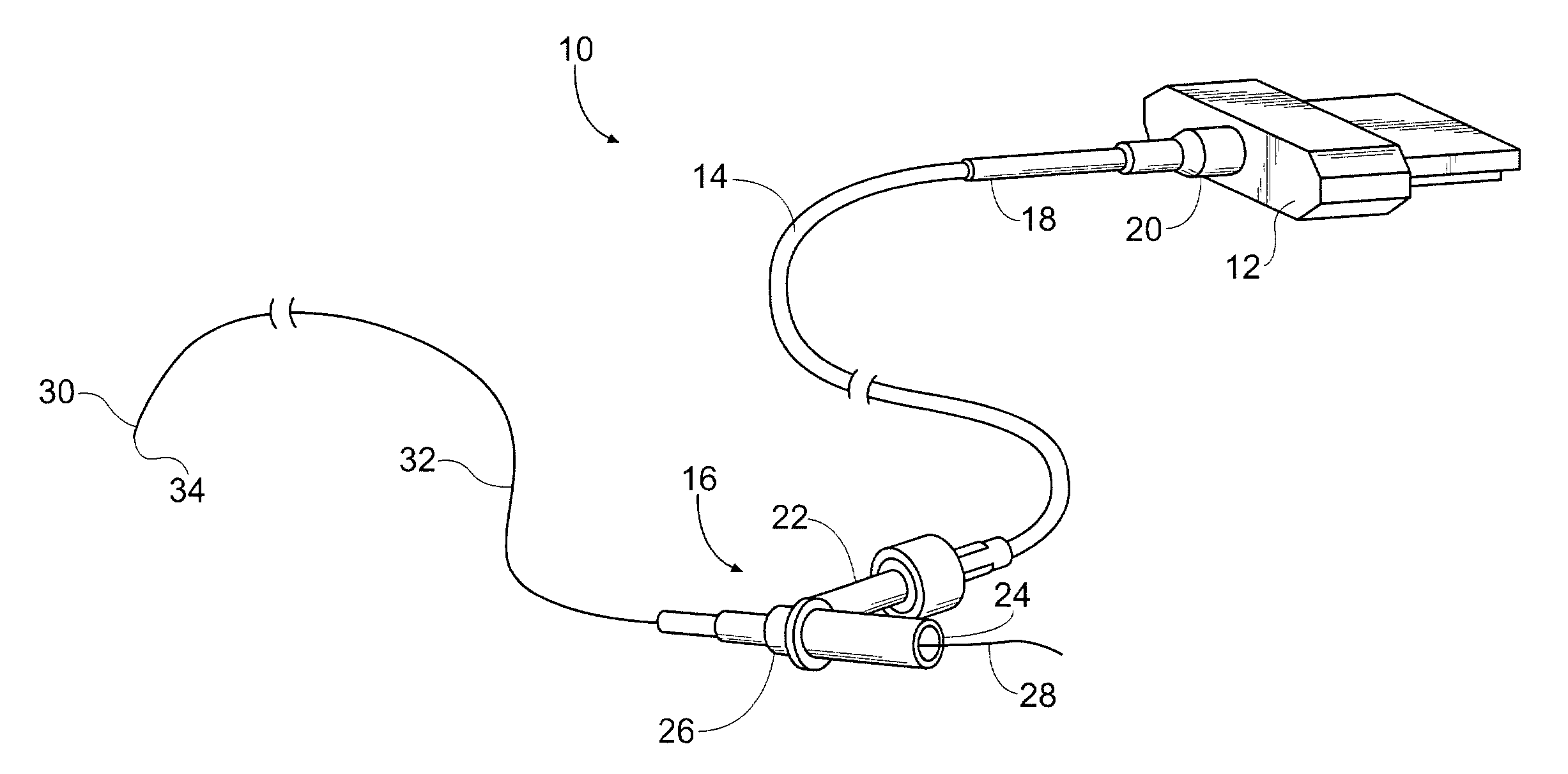
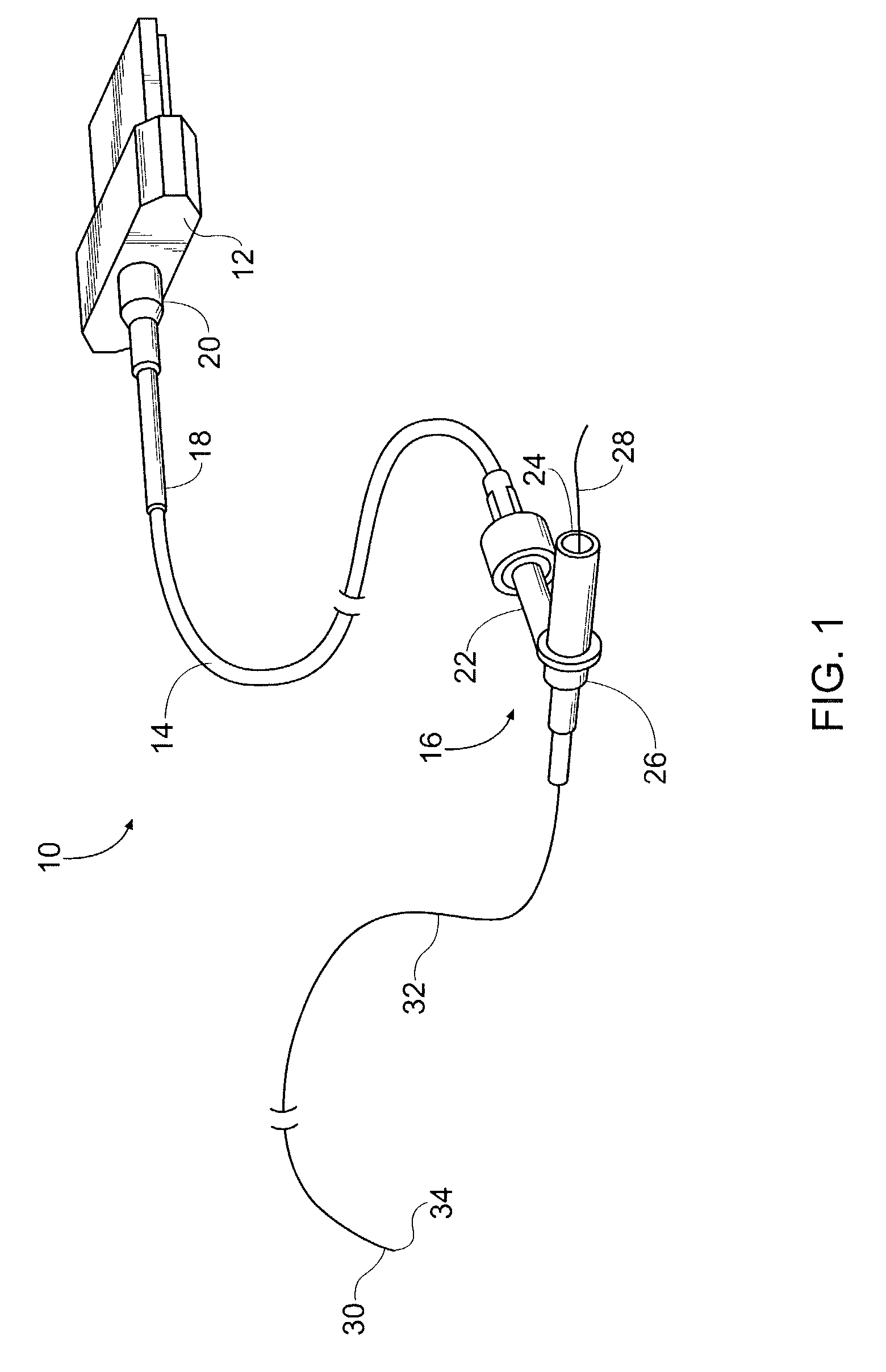
[0021]FIG. 1 is a perspective view of a fiber optic-catheter assembly 10 and proximal coupler 12. As noted earlier, the proximal coupler provides an interface between the fiber optic-catheter assembly 10 and a light source (e.g., laser, not shown). The assembly 10 includes a light conveying cable 14, which contains optical fibers that direct light from the proximal coupler 12 to a bifurcating adapter 16. A proximal end 18 of the cable 14 includes a strain relief sleeve 20, which is typically made of coiled metal or an elastomer and helps reduce damage to the assembly 10 due to forces exerted on the cable 14 during handling. Note that throughout the specification the terms “proximal” and “distal” refer to the location of a component of the assembly 10 relative to the light source-a component that is nearer to the light source is “proximal,” whereas a component that is further away from the light source is “distal.”

[0022]As shown in FIG. 1, the bifurcating adapter 16 includes a pair o...


PUM


Abstract

A coupler for interfacing a light source, such as a laser, and a fiber optic cable is disclosed. The coupler includes a slide mount having a channel that is adapted to receive optical fibers. The channel extends from a proximal end of the slide mount to a distal end of the slide mount. The proximal end of the slide mount is adapted to fit into an aperture of the light source and the distal end of the slide mount is adapted to transmit light to the fiber optic cable. The coupler also includes a clamp that is mounted on the slide mount adjacent to its proximal end. The clamp covers at least a portion of the channel, thereby securing the optical fibers within the channel without the use of an adhesive.

Description

[0001]This application claims priority to U.S. Provisional Application Ser. No. 60 / 368,725, filed on Mar. 29, 2002.FIELD OF THE INVENTION[0002]The present invention relates to optical waveguides that employ mechanical connectors for coupling a light source to the waveguide, and more particularly, to mechanical couplers for terminating optical fibers of catheters used in laser angioplasty and other medical procedures.DISCUSSION[0003]Numerous medical procedures require delivery of energy from a light source, such as a laser, through optical fibers or similar waveguides that are disposed in the body. These medical procedures include removal of arterial plaque and occlusions (laser angioplasty), extraction of cardiac pacemaker leads, destruction of tumors and calculi, and repair of bleeding vessels. The optical fibers used in the medical procedures are disposed within a flexible tube or catheter, which slides over a guide wire for routing the catheter from an entry point to a treatment ...

Claims


Application Information

Patent Timeline
Patent Type & Authority Patents(United States)
IPC IPC(8): G02B6/00A61B17/00A61B18/22G02B6/38
CPCG02B6/3833A61B18/22A61B2017/00477A61B2562/228G02B6/3862G02B6/3847G02B6/3858
Inventor HARLAN, KENNETH D.GRACE, KENNETH P.CARVER, ROBERTCOE, MICHAEL SEAN
Owner SPECTRANETICS
Why Eureka
Try Eureka