Fuel cell system and operation method having a condensed water tank open to atmosphere

a fuel cell and condensed water technology, applied in fuel cell applications, sustainable buildings, electric power generation, etc., can solve the problems of difficult to completely prevent metal ions from being eluted into recycled water, reduced electric power generation amount, and poor purity of water, etc., to achieve high efficiency, low cost, and simple construction

Inactive Publication Date: 2006-05-30
PANASONIC CORP
View PDF12 Cites 36 Cited by
  • Summary
  • Abstract
  • Description
  • Claims
  • Application Information

AI Technical Summary

Benefits of technology

[0015]In consideration of the above-described first to third problems of the conventional polymer electrolyte fuel cell system, an object of the present invention is to provide a polymer electrolyte fuel

Problems solved by technology

There is a problem in that conductive ions are eluted into the cooling pure water from the heat exchanger 5, which cools the cooling water, and the increased conductive ions cause short-circuit in the fuel cell 1, thereby reducing the amount of electric power generation.
Thus, the water is quite inferior in purity.
However, in order to construct a practical system, some parts, such as a pipe and a valve, have to be made of metal in terms of safety or thermal efficiency, and it is difficult to entirely prevent metal ions from being eluted into the recycled water.
Thus, there is a first problem in that the cooling water tank 2 and the cooling water channel 3 need to be constructed so as to withstand the pressure variation caused by the temperature variation.
However, there is a second problem in that the cost is increased by the increase i

Method used


Image

  • Fuel cell system and operation method having a condensed water tank open to atmosphere
  • Fuel cell system and operation method having a condensed water tank open to atmosphere
  • Fuel cell system and operation method having a condensed water tank open to atmosphere

Examples


first embodiment

[0133](First Embodiment)

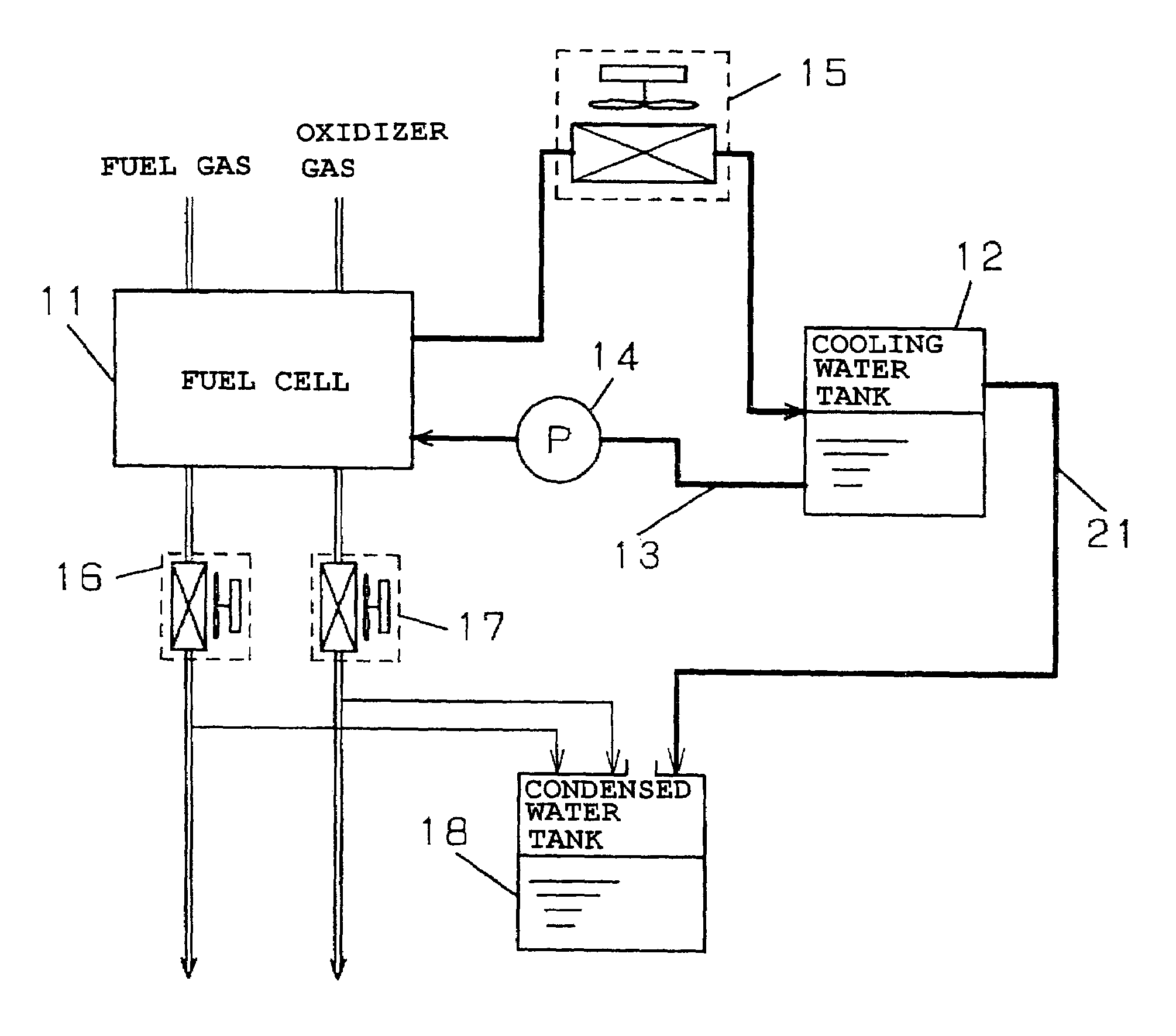
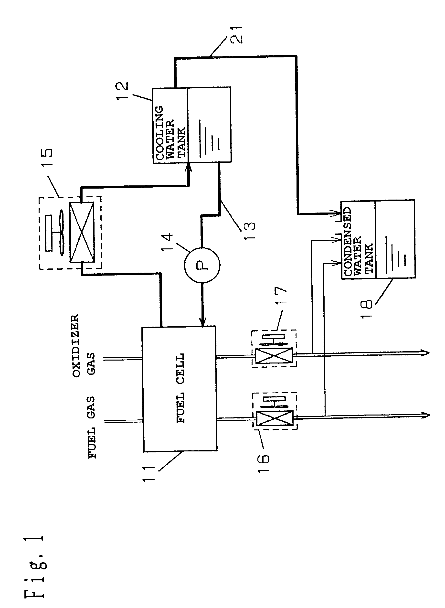
[0134]FIG. 1 is a block diagram showing a polymer electrolyte fuel cell system according to a first embodiment of this invention. The polymer electrolyte fuel cell system comprises a polymer electrolyte fuel cell 11 for generating electric power using a fuel gas and an oxidizing gas, a cooling water tank 12 for storing cooling water for cooling the fuel cell 11, a cooling water channel 13 for circulating the cooling water, a cooling water pump 14 serving as means of making the cooling water circulate through the cooling water channel 13, a heat exchanger 15 for cooling the cooling water, a fuel-side condenser 16 for cooling the exhaust fuel gas discharged from the fuel cell 11 to condense water vapor contained therein, an oxidizer-side condenser 17 for cooling the exhaust oxidizer gas discharged from the fuel cell 11 to condense water vapor contained therein, a condensed water tank 18 opened to the atmosphere for storing the water condensed in the fuel-side c...

second embodiment

[0146](Second Embodiment)

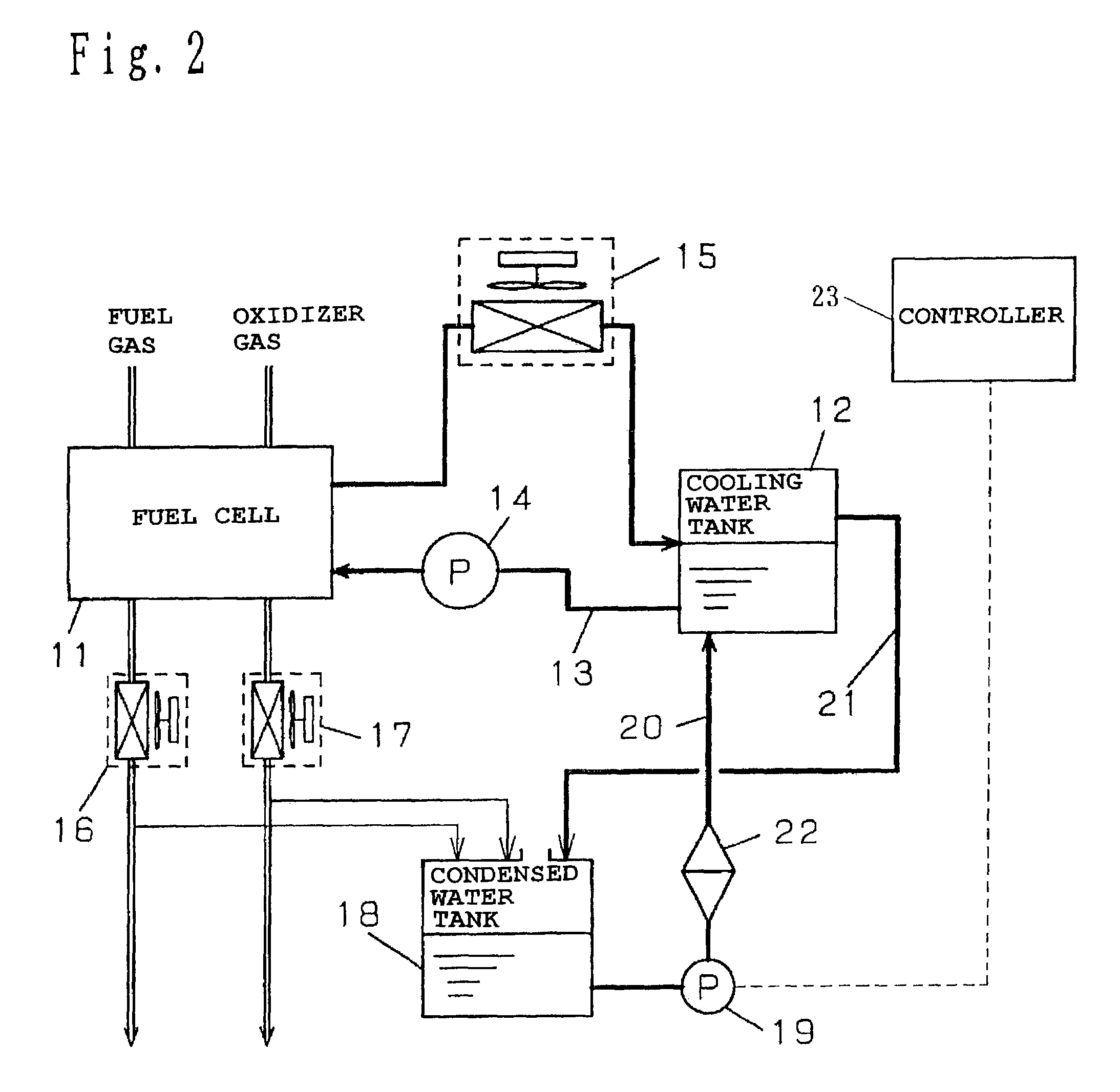
[0147]FIG. 2 is a block diagram showing a polymer electrolyte fuel cell system according to a second embodiment of this invention. Members identical to those in FIG. 1 and having the same functions as in FIG. 1 are given the same reference numerals, and description thereof will be omitted.

[0148]This embodiment is different from the first embodiment in that there are provided a water supply channel 20, which is provided with an ion removal filter 22 and a water supply pump 19 for feeding the condensed water from the condensed water tank 18 to the cooling water tank 12, and a controller 23 for controlling activation of the water supply pump 19. The ion removal filter 22 serves as means of treating water quality.

[0149]Now, the operation will be described. When the cooling water in the cooling water tank 12 is decreased, the water supply pump 19 in the water supply channel 20 is activated under the control of the controller 23, thereby supplying the water in the...

third embodiment

[0162](Third Embodiment)

[0163]FIG. 3 is a block diagram showing a polymer electrolyte fuel cell system according to a third embodiment of this invention. Members identical to those in FIG. 2 and having the same functions as in FIG. 2 are given the same reference numerals, and description thereof will be omitted.

[0164]In the polymer electrolyte fuel cell system according to this embodiment, the controller 23 comprises number-of-operations storage means 24 of counting and storing the number of operations of the system and number-of-operations resetting means 25 of resetting the number of operations to an initial condition.

[0165]The number-of-operations storage means 24 newly stores a value n+1, which is obtained by adding 1 to the number of operations n, after the system operation is terminated. Besides, the number-of-operations resetting means 25 changes the number of operations n in the number-of-operations storage means 24 to 0, the initial condition, after the operation of the wat...


PUM


Abstract

To avoid pressure variation in a cooling water channel, extend a life of an ion exchange resin used to maintain quality of cooling water and reduce power consumption by auxiliary machinery at low cost. There is provided a polymer electrolyte fuel cell, a cooling water tank, a cooling water channel, a cooling water pump, a heat exchanger, a fuel-side condenser and an oxidizer-side condenser that cool exhaust fuel gas and exhaust oxidizer gas discharged from the fuel cell to condense content water vapor, a condensed water tank that stores the water condensed in the fuel-side condenser and the oxidizer-side condenser, a water supply channel having a water supply pump for feeding the condensed water to the cooling water tank, and a water discharge channel for the cooling water tank.

Description

[0001]This application is a U.S. National Phase application of PCT International application PCT / JP01 / 09133.TECHNICAL FIELD[0002]The present invention relates to a fuel cell system that uses a fuel cell to generate electric power, a method of operating the same and the like.BACKGROUND ART[0003]A conventional polymer electrolyte fuel cell system will be described below step-by-step.[0004]First, FIG. 16 is a block diagram showing the conventional polymer electrolyte fuel cell system. A cooling water circulating system is provided, in which cooling pure water is supplied from a cooling water tank 2 to a polymer electrolyte fuel cell 1 through a cooling water channel 3 by means of a cooling water pump 4, and the cooling pure water having passed through the fuel cell 1 is cooled in a heat exchanger 5, such as a radiator, and then returns to the cooling water tank 2.[0005]There is a problem in that conductive ions are eluted into the cooling pure water from the heat exchanger 5, which coo...

Claims


Application Information

Patent Timeline
IPC IPC(8): H01M8/04H01M8/06
CPCH01M8/04029H01M8/04044H01M8/04164H01M8/0606H01M8/04052H01M2250/405Y02B90/16Y02E60/50Y02B90/10H01M8/04H01M8/06
Inventor NAKAMURA, AKINARINAKAYAMA, TATSUOUEDA, TETSUYAOZEKI, MASATAKA
Owner PANASONIC CORP
Why Eureka
Try Eureka