Optical bidirectional module

a bidirectional module and optical technology, applied in optics, instruments, optical light guides, etc., can solve the problem of difficult to maximize the efficiency of one zerosup>th/sup>-order diffraction, and achieve the effect of maximizing each diffraction efficiency and low cost high performan

Inactive Publication Date: 2006-06-06
KONICA MINOLTA INC
View PDF3 Cites 6 Cited by
  • Summary
  • Abstract
  • Description
  • Claims
  • Application Information

AI Technical Summary

Benefits of technology

[0006]An object of the invention is to provide a low-cost high performance optical bidirectional module which is able to maximize each diffraction efficiency of different orders for light beams with different wavelengths, in view of problems of the conventional technique mentioned above.
[0007]In order to accomplish the above objectives, the optical bidirectional module of the invention is what mixes and separates optical signals with different wavelengths used for bidirectional optical fiber communication by means of a wavelength multiplex system, and has a light emitting element which transmits optical signals to the end facet of the optical fiber, a light receiving element which receives optical signals coming from the end facet of the optical fiber and a stair-shaped multi-level grating so that the stair-shaped multi-level grating can separate efficiently the first light path between the end facet of optical fiber and the light emitting element from the second light path between the end facet of optical fiber and the light receiving element because of the different wavelengths of the respective light signals.
[0008]It is possible to maximize diffraction efficiency of different order diffraction for light beams with different wave lengths and also possible to realize a low-cost high performance optical bidirectional module with this optical bidirectional module, wherein the stair-shaped multi-level grating separates efficiently a light path between an end facet of optical fiber and a light emission device from another light path between the end facet of optical fiber and a light receiving element by means of different wavelengths of respective light signals.

Problems solved by technology

However, when the two-level grating is employed for diffraction grating 600, it is difficult to maximize zeroth-order diffraction efficiency for another light with wavelength λ0, because each dimension of grating structure such as groove depth d, groove width W and pitch of grooves P are determined automatically based on the maximum condition of first-order diffracted light ray with wavelength λ1 which is given by λ1 / {2(n−1)}.

Method used


Image

  • Optical bidirectional module
  • Optical bidirectional module
  • Optical bidirectional module

Examples


Embodiment Construction

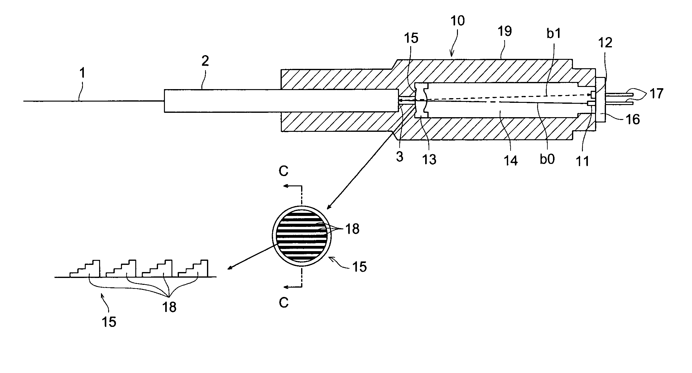
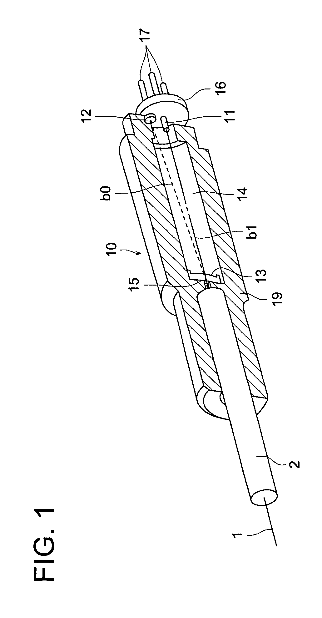
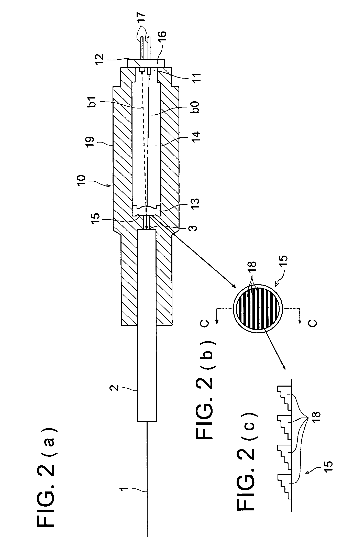
[0041]A preferred embodiment to practice the invention will be explained by referring to drawings. FIG. 1 is a perspective view showing an internal structure of the halved optical bidirectional module of the preferred embodiment. FIG. 2 shows longitudinal cross-sectional view (a) of optical bidirectional module main parts in FIG. 1, enlarged plan view (b) of a grating formed on the coupling lens shown in FIG. 1 and schematic cross-sectional view (c) of the grating structure taken on line C—C.

[0042]As illustrated in FIG. 1 and FIG. 2(a), optical bidirectional module 10 having light emitting element 11, light receiving element 12 and coupling lens 13 in a long, substantially cylindrical casing 19. The light emitting element 11 and light receiving element 12 are installed on a common base 16, which is fixed to the casing, and electrically connected with plural connecting pins 17 projecting outward from the base 16.

[0043]Fiber holder 2 which holds optical fiber 1 is inserted and fixed i...


PUM


Abstract

An optical bidirectional module 10 having therein light emitting element 11 which transmits optical signal to the end facet of the optical fiber, light receiving element 12 which receives optical signal from the end facet of the optical fiber and stair-shaped multi-level grating 15, wherein the stair-shaped multi-level grating separates the first light path between the end facet of optical fiber and the light emitting element and the second light path between the end facet of optical fiber and the light receiving element by a different wavelength of each optical signal, when the module mixes and separates optical signal with different wavelengths traveling in opposite directions related to the end facet of the optical fiber 1, used for bidirectional optical fiber communication by means of a wavelength multiplex system.

Description

BACKGROUND OF THE INVENTION[0001]The present invention relates to an optical bidirectional module used for transmission and reception terminals for bidirectional optical fiber communication by means of a wavelength multiplex system.[0002]In optical communication systems by means of optical transmission lines such as optical fiber lines, plural optical signals with different wavelengths are transmitted simultaneously through optical fiber by means of WDM (Wavelength Division Multiplex System), and bidirectional optical transmission modules are used in transmission and reception terminals for optical signals. A bidirectional optical transmission module of this kind is known by, for example, Patent Document 1 indicated below. This bidirectional optical transmission module contains light emitting element 100 and light receiving element 700 in a common package 120 and has holographic diffraction grating 600 on the upper or lower surface of cover glass 220 at an aperture of the package as...

Claims


Application Information

Patent Timeline
Patent Type & Authority Patents(United States)
IPC IPC(8): G02B6/34G02B6/42G02B6/35G02B6/36
CPCG02B6/4246G02B6/4214G02B6/29308G02B6/2931G02B6/29311
Inventor OZEKI, YUKIHIROFURUTA, KAZUMIUEDA, HIROAKIKUISEKO, MANAMISEKINE, KOUJIROUYOKOYAMA, MITSURUMITSUGI, NAOKIHORII, KOJI
Owner KONICA MINOLTA INC
Why Eureka
Try Eureka