Device and method for artificial insemination of bovines and other animals

a technology for insemination and bovines, which is applied in the field of artificial insemination devices and bovines, can solve the problems of affecting the insemination efficiency and conception rate, and affecting the insemination efficiency and conception success rate, so as to improve the positioning of the distal end, less spoilage, and less spoilage of semen

Inactive Publication Date: 2006-06-06
UNIV GENT
View PDF8 Cites 17 Cited by
  • Summary
  • Abstract
  • Description
  • Claims
  • Application Information

AI Technical Summary

Benefits of technology

[0033]The use of inner and outer sheath makes it possible to provide an improved positioning of the distal end of the AI device according to the invention. The use of three elements results in a suitable site of deposition for the semen, i.e. near the utero-tubal junction. This suitable deposition site is obtained via two main steps. First step is performed mainly by the introduction of the rigid outer sheath, which encloses at least the distal part of the inner sheath and the semen tube. The distal end of the outer sheath is positioned through the cervix of the vagina and extends close to the uterine wall. A subsequent positioning step is obtained via the protrusion of at least a flexible part i.e. the distal end of the inner sheath jointly with the semen tube through the outer sheath. Due to the flexible material of the distal end of the inner sheath and the semen tube a curve is made such that the distally extendillg end reaches easily a position near the UTJ. This second positioning step is preferably controlled by manual guidance of the distal end of the protruded flexible part of the inner sheath and the semen tube. Once in a suitable position near the utero-tubal junction semen is ejected. The semen introduction near the UTJ is performed with less spoilage due to the fact that the semen tube is a separate element housed in the inner sheath. The semen is during the expelling operation protected by the enveloping or covering action of the inner sheath, which is especially adapted therefor. The inner sheath is provided with a flexible distal part and suitable closure means for partially closing off the semen tube. As a consequence less spoilage of semen occurs during the overall positioning of the combination semen tube and inner sheath. The introduction of the semen is an intentional and controlled action once the distal end of the inner sheath with the expelling opening for the semen has reached a suitable position near the utero-tubal junction. The semen is expelled with a specific action such as an air pressure pulse performed on the proximal end of the semen tube. The semen is forced out of the semen tube only when it is in a suitable deposition site. The distal end of the semen tube is enclosed in the inner sheath. Preferably the distal end of the semen tube is in a frictional contact with the inner wall of the inner sheath. When the inner sheath protrudes through the outer sheath, the semen tube will—passively—follow the movement of the inner sheath.
[0034]In a preferred embodiment an artificial insemination is provided wherein the inner sheath comprises at least a rigid part and a flexible part. The use of said flexible part provides an advantage, i.e. has the possibility of following the curvature of the uterine horn without damaging the uterine wall. In the preferred embodiment the distal end (introduced in the cervix and uterus) of the flexible part is provided with a cervix protector element having at least one ejection port which preferably extends at least partially in the radial direction of the inner sheath. Such a specific ejection port is suitable for ejection of semen when required and closes off the outer sheath and the semen tube during their positioning. Provided with said cervix protector element the joint introduction of the outer sheath and the semen tube can be performed with lowered risk of harm to the cervix of the bovine to be inseminated.

Problems solved by technology

Hence there is the ever present danger of perforating the wall of the cervix or the uterus with the inseminating tube, causing injury to the animal.
Because of these difficulties, it is often impossible to advance the inseminating tube very far into the cervix, with a corresponding lower insemination efficiency and conception success rate.
While these devices and methods have been a great advancement in artificial insemination, reducing time, expenses and effort, and increasing effectiveness, there are still a number of problems.
The major disadvantage of the deposition of the semen at the posterior end of the uterus is the great loss (about 60%) of the inseminated semen.
One problem is that these devices do not deliver the optimum quantity and concentration of semen that will maximize the probability of conception since there is no way to assure that all of the semen is transferred from its storage straw into the uterus of the animal without any losses.
Another problem is that these devices do not simplify the deliverance of the optimum insemination dose and diluting fluid required to accommodate the cervices and uteri of animals of varying sizes since there is no way to vary the dose while preserving the optimum quantity and concentration of semen.
The distance of the ejected semen towards the mature ovum in the oviduct remains considerable and results in a lower insemination efficiency and conception success rate.
Because palpation of the ovaries often causes rupture of the mature follicle and loss of the occyte in the abdomen, the side of the ovulation is usually not determined during insemination.
The use of such a tube is only possible in a recti-linear manner.
It is impossible to move the cotton plugs and the polyvinyl chloride forward through the teflon tube if it makes a sharp curvature of the contractile uterus of a cow.
In these known methods semen is lost at various steps of the operation.
These losses of semen produce an inseminating fluid charge with a low sperm concentration and a corresponding low fertilization success rate.
In addition, the insemination dose and diluting fluid cannot be readily adjusted to accommodate the various sizes of cervix and uterus found among animals of different sizes, breeds and species.

Method used


Image

  • Device and method for artificial insemination of bovines and other animals
  • Device and method for artificial insemination of bovines and other animals
  • Device and method for artificial insemination of bovines and other animals

Examples


Embodiment Construction

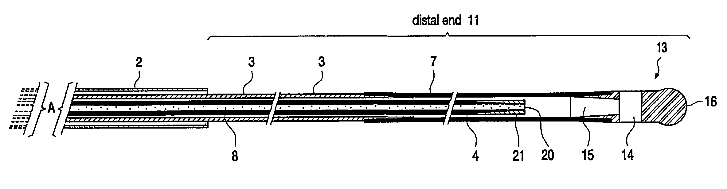
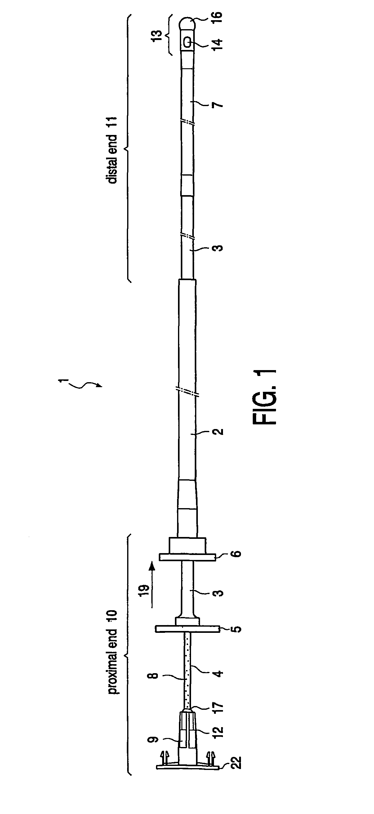
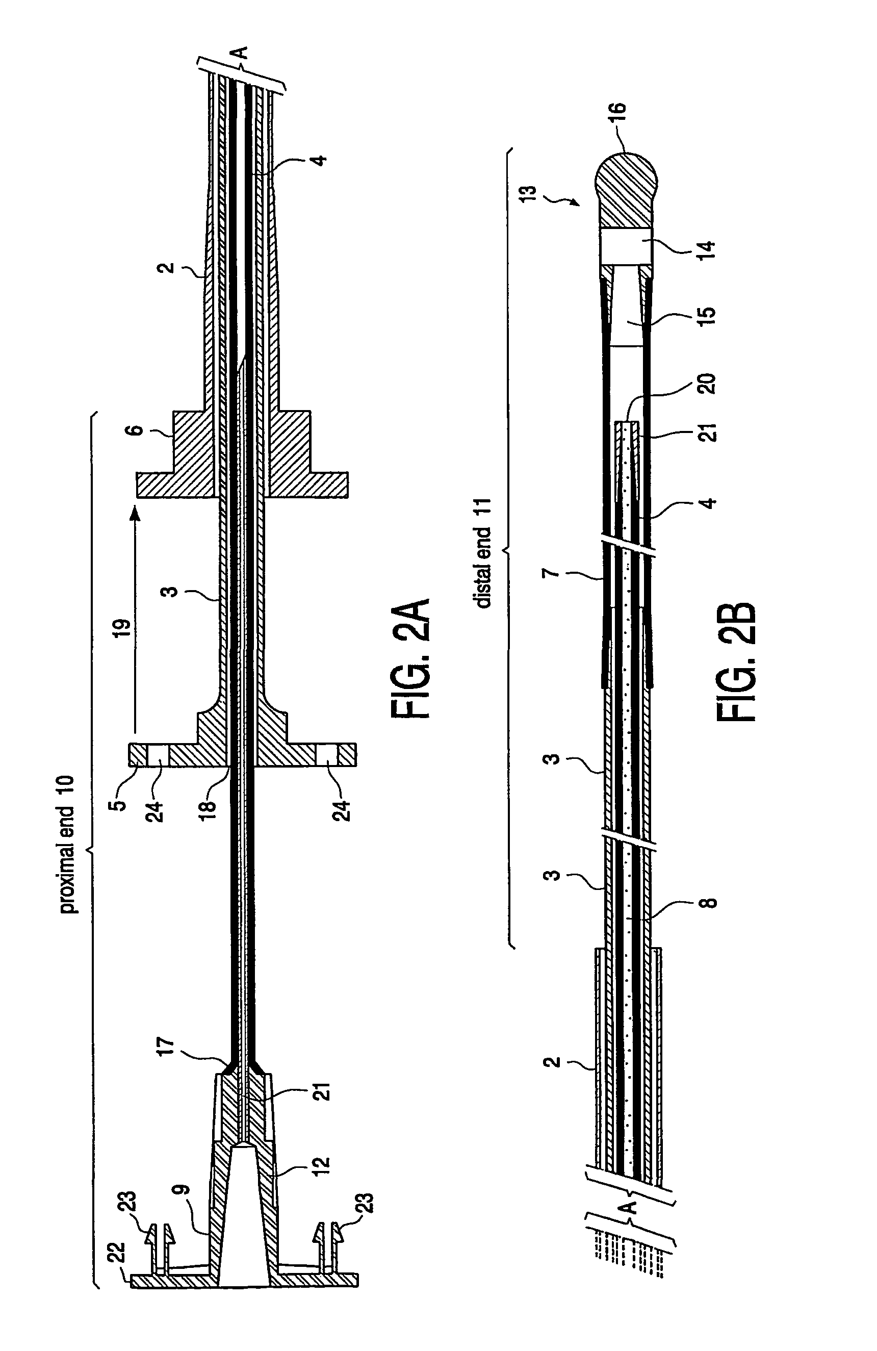
[0040]The entire artificial insemination assembly 1 comprises three hollow cylindrical open or semi-open tubular elements, which are each axially movable in a sliding motion mounted in one another as shown in FIG. 1. These three elements are: an outer protective and rigid sheath 2 suitable for the penetration of the cervix, an inner sheath 3 and the semen tube 4. The diameter of those three elements is such that the semen tube 4, having the smallest diameter, is axially movable in the inner sheath 3, and the inner sheath 3 is axially movable in the outer sheath 2. The outer sheath 2 has a length which is smaller than the length of the inner sheath 3 and is made out a rigid material suitable for penetrating the cervix.

[0041]The proximal end 10 of the AI device 1 is the end which protrudes out of the bovine during insemination allowing at all times a manipulation of the outer and the inner sheath and of the semen tube at which ends an external manual handling is performed. The distal ...


PUM


Abstract

An artificial insemination (AI) device for the insemination of bovines and other animals including three hollow and essentially cylindrical tubular elements. Each element is provided with an open proximal and an open distal end, the three elements being: an outer protective sheath, an inner sheath, and a semen tube, whereby the diameter of the elements is such that the inner sheath is axially movable in the outer protective sheath and the semen tube is axially movable in the inner sheath, whereby the length of the outer sheath is less than the length of the inner sheath and whereby the inner sheath and the semen tube are jointly axially displaceable in and through the outer sheath. An outer sheath, an inner sheath and a semen tube for use in an AI device and a method for the insemination of bovines and other animals, includes the steps of inserting through the cervix and into the uterine horn, a closed tubular element to a point near the major curve of the horn, opening the tubular element by protrusion of an inner tubular element and manually guiding it into the curve of the horn and positioning the distal end of the inner tubular element near the ovary, and further providing semen nearby the UTJ through an internal semen channel.

Description

RELATED APPLICATIONS[0001]This application is a national phase entry in the United States of the International Application PCT / EP01 / 10181 filed Sep. 4, 2001, and claims the benefit of Application 00870190.6 filed Sep. 5, 2000, in the European Patent Office.FIELD OF THE INVENTION[0002]The present invention relates to a method and a device for the artificial insemination of bovines and other animals.DESCRIPTION OF RELATED ART[0003]Worldwide, artificial insemination (AI) has penetrated about 80% of the dairy industry but only about 5% of the beef producing industry. One reason is the need for skilled personnel, veterinarians and technicians, trained to grasp the cervix via the rectum and to guide the AI pipette into or through the cervix.[0004]In the traditional AI, the inseminator must insert the insemination tube into the cervix by developing the tactile skill to work through the wall of the large intestine while pushing the tube forward through the vagina with the other hand. The ce...

Claims


Application Information

Patent Timeline
Patent Type & Authority Patents(United States)
IPC IPC(8): A61B17/43A61D19/02
CPCA61D19/027Y10S604/906
Inventor VERBERCKMOES, STEVENVAN SOOM, ANNDE KRUIF, AART
Owner UNIV GENT
Why Eureka
Try Eureka