Information additive code generator and decoder for communication systems

a technology of information additive and communication system, applied in the field of encoding and decoding data in communications system, can solve the problems of loss of data (erasure receiver will receive many useless duplicate segments)

Inactive Publication Date: 2006-06-06
QUALCOMM INC
View PDF16 Cites 53 Cited by
  • Summary
  • Abstract
  • Description
  • Claims
  • Application Information

AI Technical Summary

Benefits of technology

[0023]One advantage of the present invention is that it does not require that the recipient begin receiving at any given point in the transmission and it does not require that the sender stop after a set number of output symbols are generated, since the sender can send an effectively unbounded set of output symbols for any given input file. Instead, a recipient can begin reception when it is ready, and from wherever it can, and can lose packets in a random pattern, and still have a good chance that the great majority of the data received is “information additive” data, i.e., data that helps in the recovery process rather than being duplicative of information already available. The fact that independently generated (often randomly unrelated) data streams are coded in an information additive way leads to many advantages in that it allows for multiple source generation and reception, erasure robustness and uncoordinated joins and leaves.

Problems solved by technology

Lost data (erasures) are often easier to deal with than garbled data (errors) because the recipient cannot always tell when garbled data is data received in error.
In a typical multiple sender system sending one file to a receiver, if the senders do not coordinate which data they will transmit and when, but instead just send segments of the file, it is likely that a receiver will receive many useless duplicate segments.
If the sender just sends segments of the original file and some segments are lost, it is likely that a receiver will receive many useless duplicate segments before receiving one copy of each segment in the file.
However, TCP is often not suitable for one-to-many or many-to-many communications or where the sender and the recipient independently determine when and where they will transmit or receive data.
On the Internet, packet loss often occurs because sporadic congestion causes the buffering mechanism in a router to reach its capacity, forcing it to drop incoming packets.
Although acknowledgment-based protocols are generally suitable for many applications and are in fact widely used over the current Internet, they are inefficient, and sometimes completely infeasible, for certain applications.
In particular, acknowledgment-based protocols perform poorly in networks with high latencies, high packet loss rates, uncoordinated recipient joins and leaves, and / or highly asymmetric bandwidth.
High latency is where acknowledgments take a long time to travel from the recipient back to the sender.
High latency may result in the overall time before a retransmission being prohibitively long.
High packet loss rates also cause problems where several retransmissions of the same packet may fail to arrive, leading to a long delay to obtain the last one or last few unlucky packets.
In the typical system, if a recipient joins and leaves an ongoing transmission without coordination of the senders, the recipient will likely perceive a loss of large numbers of packets, with widely disparate loss patterns perceived by different recipients.
Asymmetric bandwidth may make it prohibitively slow and / or expensive for the recipient to acknowledge packets frequently and infrequent acknowledgments may again introduce delays.
Furthermore, acknowledgment-based protocols do not scale well to broadcasting, where one sender is sending a file simultaneously to multiple users.
Protocols that rely on acknowledgment data (either positive or negative) for reliable delivery of the file require a back channel from each recipient to the sender, and this can be prohibitively expensive to provide.
Furthermore, this requires a complex and powerful sender to be able to properly handle all of the acknowledgment data sent from the recipients.
Another drawback is that if different recipients lose different sets of packets, rebroadcast of packets missed only by a few of the recipients causes reception of useless duplicate packets by other recipients.
However none has been clearly adopted at this time, for various reasons.
For one, acknowledgment-based protocols also do not scale well where one recipient is obtaining information from multiple senders, such as in a low earth orbit (“LEO”) satellite broadcast network.
A major drawback with a carousel-based protocol is that if a recipient misses even one packet, then the recipient has to wait another entire cycle before having a chance at receiving the missed packet.
Another way to view this is that a carousel-based protocol can cause a large amount of useless duplicate data reception.
For example, if a recipient receives packets from the beginning of the carousel, stops reception for a while, and then starts receiving again at the beginning of the carousel, a large number of useless duplicate packets are received.
However, many erasure code solutions either fail to solve the problems of acknowledgment-based protocol or raise new problems.
One problem with many erasure codes is that they require excessive computing power or memory to operate.
This leads to inefficiencies if the loss rate of packets is overestimated, and can lead to failure if the loss rate of packets is underestimated.
This limitation is generally acceptable for many communications problems, so long as N is selected to be greater than K+A by at least the actual packet loss, but this requires an advance guess at the packet loss.
Another disadvantage of Tornado codes is that they require the encoder and decoder to agree in some manner on a graph structure.
Furthermore, the graphs needed by the Tornado codes are complicated to construct, and require different custom settings of parameters for different sized files to obtain the best performance.
These graphs are of significant size and require a significant amount of memory for their storage at both the sender and the recipient.
Thus, it is very likely that a recipient obtaining output symbols generated from the same input file using the same graph from more than one sender will receive a large number of useless duplicate output symbols.

Method used


Image

  • Information additive code generator and decoder for communication systems
  • Information additive code generator and decoder for communication systems
  • Information additive code generator and decoder for communication systems

Examples


Embodiment Construction

[0052]In the examples described herein, a coding scheme denoted as “chain reaction coding” is described, preceded by an explanation of the meaning and scope of various terms used in this description.

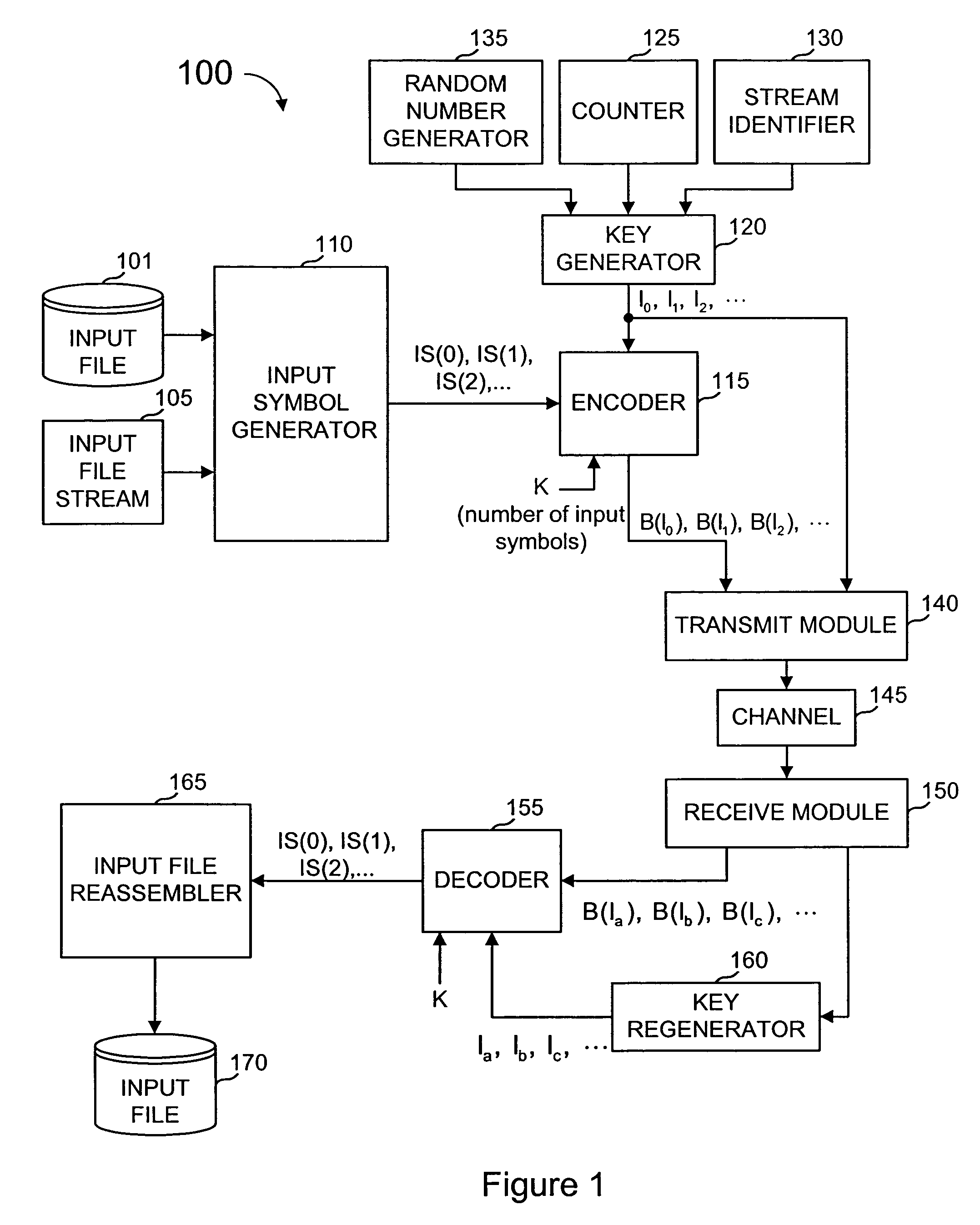
[0053]With chain reaction coding, output symbols are generated by the sender from the input file as needed. Each output symbol can be generated without regard to how other output symbols are generated. At any point in time, the sender can stop generating output symbols and there need not be any constraint as to when the sender stops or resumes generating output symbols. Once generated, these symbols can then be placed into packets and transmitted to their destination, with each packet containing one or more output symbols.

[0054]As used herein, the term “file” refers to any data that is stored at one or more sources and is to be delivered as a unit to one or more destinations. Thus, a document, an image, and a file from a file server or computer storage device, are all examples of “files”...


PUM


Abstract

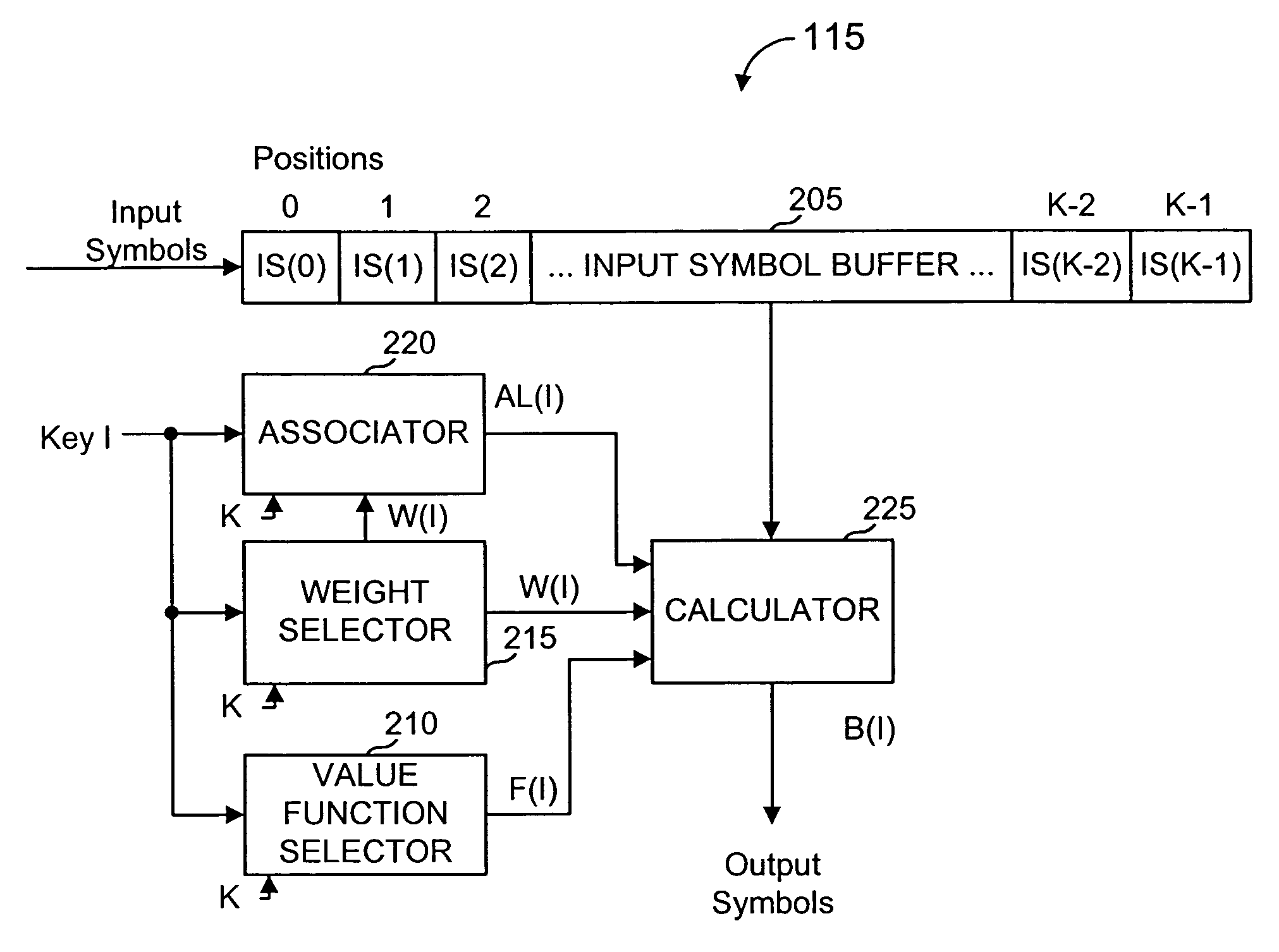
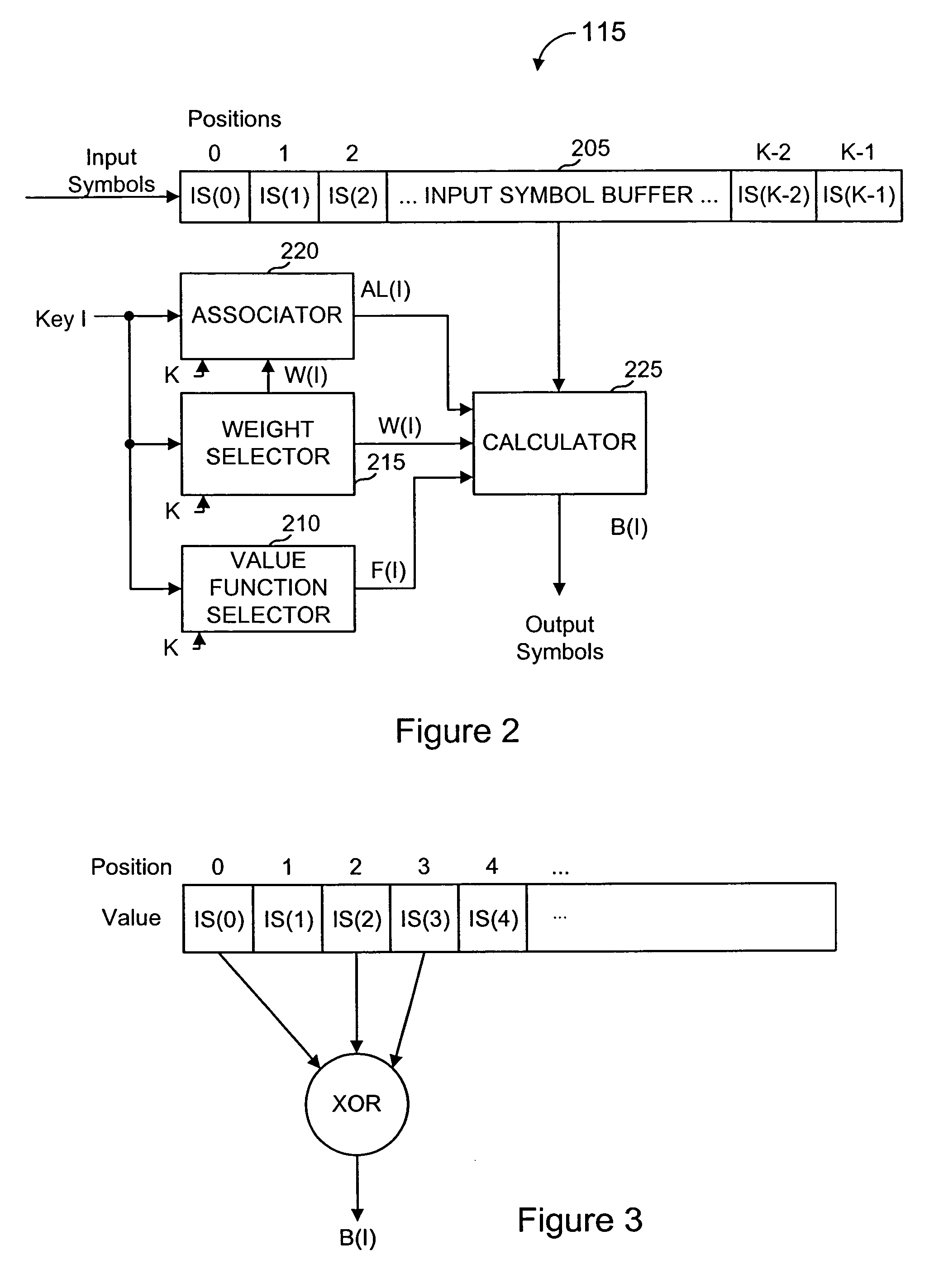
An encoder uses an input file of data and a key to produce an output symbol. An output symbol with key I is generated by determining a weight, W(I), for the output symbol to be generated, selecting W(I) of the input symbols associated with the output symbol according to a function of I, and generating the output symbol's value B(I) from a predetermined value function F(I) of the selected W(I) input symbols. An encoder can be called repeatedly to generate multiple output symbols. The output symbols are generally independent of each other, and an unbounded number (subject to the resolution of I) can be generated, if needed. A decoder receives some or all of the output symbols generated. The number of output symbols needed to decode an input file is equal to, or slightly greater than, the number of input symbols comprising the file, assuming that input symbols and output symbols represent the same number of bits of data.

Description

CROSS REFERENCES TO RELATED APPLICATIONS[0001]This application is a continuation of U.S. patent application Ser. No. 10 / 076,623, filed Feb. 14, 2002 is now an U.S. Pat. No. 6,614,366, which is a continuation of U.S. patent application Ser. No. 09 / 757,078, filed Jan. 8, 2001 is now an U.S. Pat. No. 6,373,406, which is a continuation of U.S. patent application Ser. No. 09 / 246,015, filed Feb. 5, 1999, issued as U.S. Pat. No. 6,307,487, which claims priority to U.S. Provisional Patent Application No. 60 / 101,473, filed Sep. 23, 1998, now abandoned, the disclosures of which are incorporated herein by reference for all purposes.BACKGROUND OF THE INVENTION[0002]The present invention relates to encoding and decoding data in communications systems and more specifically to communication systems that encode and decode data to account for errors and gaps in communicated data, and to efficiently utilize communicated data emanating from more than one source.[0003]Transmission of files between a se...

Claims


Application Information

Patent Timeline
Patent Type & Authority Patents(United States)
IPC IPC(8): H03M11/00G06F11/10H03M13/11H03M13/37H04L1/00H04L12/18H04L12/28H04L12/56
CPCH03M13/1191H03M13/373H03M13/3746H03M13/3761H04L12/1836H04L1/0041H04L1/0045H04L1/0057H04L1/004H04L7/00
Inventor LUBY, MICHAEL G.
Owner QUALCOMM INC
Why Eureka
Try Eureka