Time interval measurement device

a time interval measurement and time interval technology, applied in the field of time interval measurement devices, can solve the problems of limited accuracy, mainly limited, and the resolution of this method given by the reference clock frequency, and achieve the effects of reducing the errors caused by phase noise in the clock signal and in the sampler, reducing the errors caused by the quantization of samples in the analog-to-digital converter and the additive noise in the filter respons

Inactive Publication Date: 2006-06-06
PANEK PETR +1
View PDF4 Cites 4 Cited by
  • Summary
  • Abstract
  • Description
  • Claims
  • Application Information

AI Technical Summary

Benefits of technology

[0019]The invention is intended for accurate measurement of the time interval between events represented by pulse signals. Its principle of operation is based on the conversion of measurement of a time interval to measurement of a sequence of samples of the response of a surface acoustic wave filter excited at the beginning and at the end of the measured interval. The advantage of the invention is the possibility to measure the time intervals with high accuracy and with practically unlimited dynamic range and resolution. The high accuracy may be achieved with relatively low clock frequency and thus not very high demand for the speed of the digital circuits used and the analog-to-digital converter.
[0020]Converting the measurement of the time interval into the measurement of a sequence of many samples allows various measurement errors to be reduced by using post-processing based on the cross-correlation technique. It can be demonstrated that the errors caused by phase noise in the clock signal and in the sampler are reduced by increasing the sampling frequency and the duration of the filter response. In turn, the errors caused by the sample quantization in the analog-to-digital converter and by an additive noise in the filter response are reduced by increasing the mean frequency and the energy of the filter response. Thus, by using a filter with appropriate parameters, a high-enough sampling frequency, and a low-jitter sampler, it is possible to achieve a very high level of accuracy, which is otherwise very difficult to achieve using current methods.

Problems solved by technology

Resolution of this method is given by the reference clock frequency, which is mainly limited by the speed of the digital circuitry in the counter.
The accuracy of this method is limited by the accuracy and stability of the phase shift between the individual clock signals.
Due to the temperature instability of the integration time constant, the integrating interpolator has to be calibrated continuously.
Its accuracy is limited by the noise and disturbances in the integrator circuitry, and by the non-linearity of the integrator.
The accuracy is mainly limited by the frequency instability and by the phase fluctuations of the started oscillators.
The accuracy of the interpolation by means of the delay line is primarily limited by the differences in the delays of the individual elements.
However, the above condition is difficult to meet in designing the delay line.
In the design of the ring delay line it is practically impossible.
The accuracy is further limited by the fast components of the noise in the delay line, which cannot be reduced by DLL or PLL stabilization.

Method used


Image

  • Time interval measurement device
  • Time interval measurement device
  • Time interval measurement device

Examples


Embodiment Construction

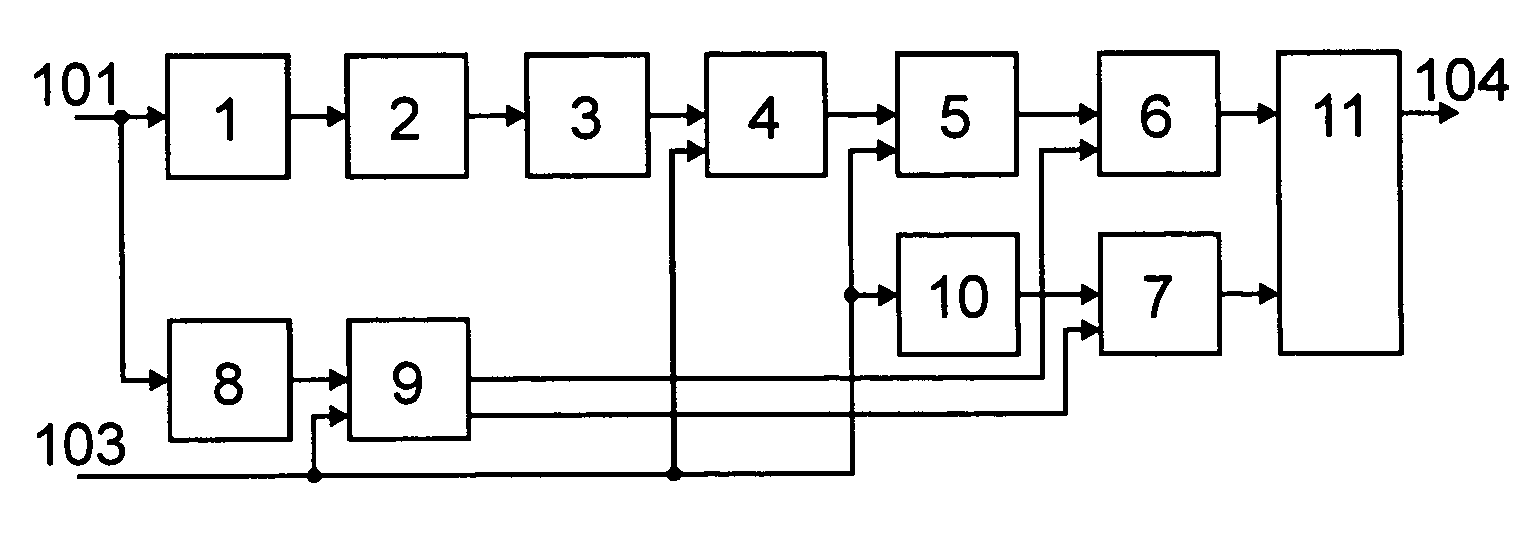
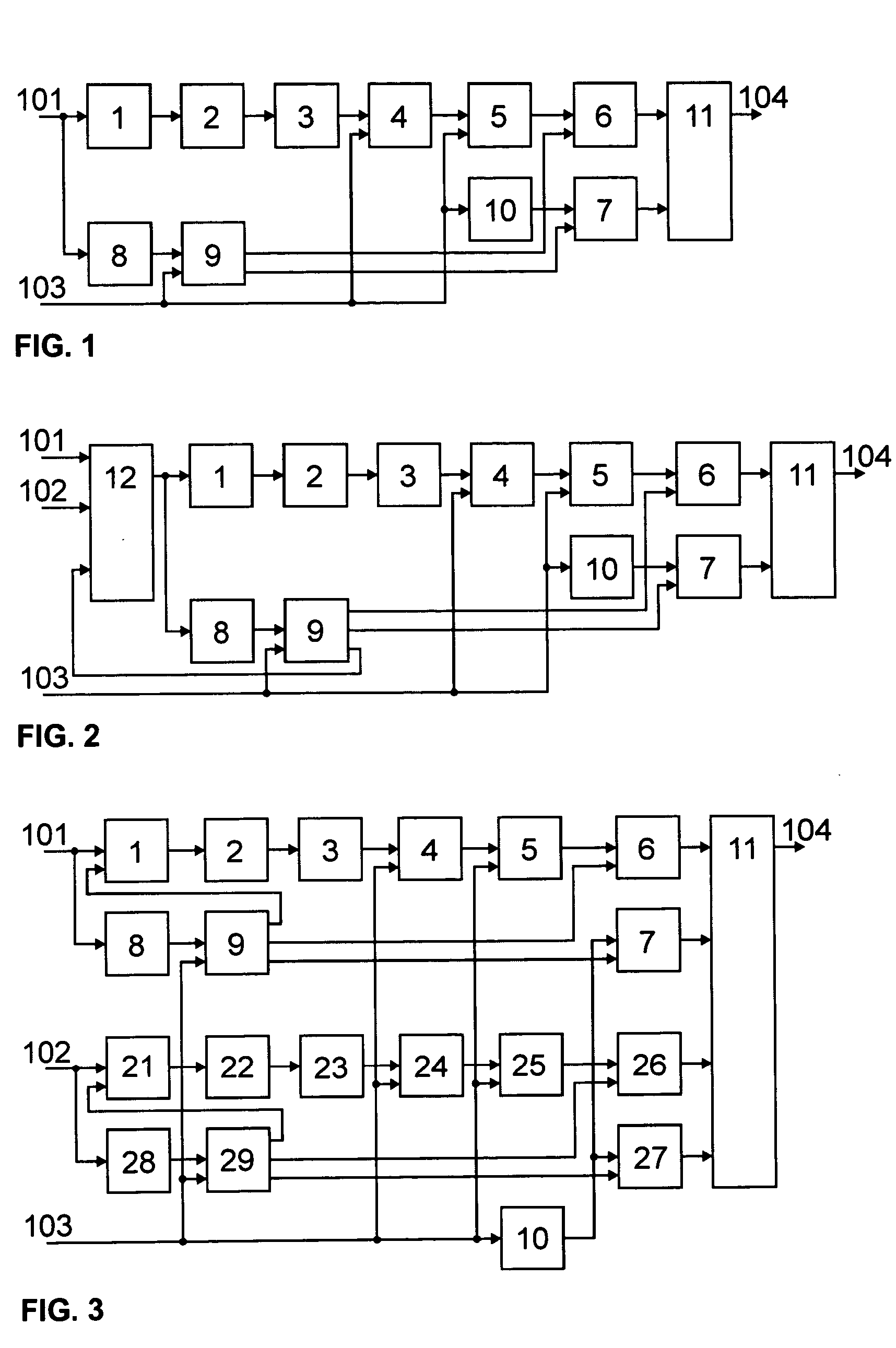
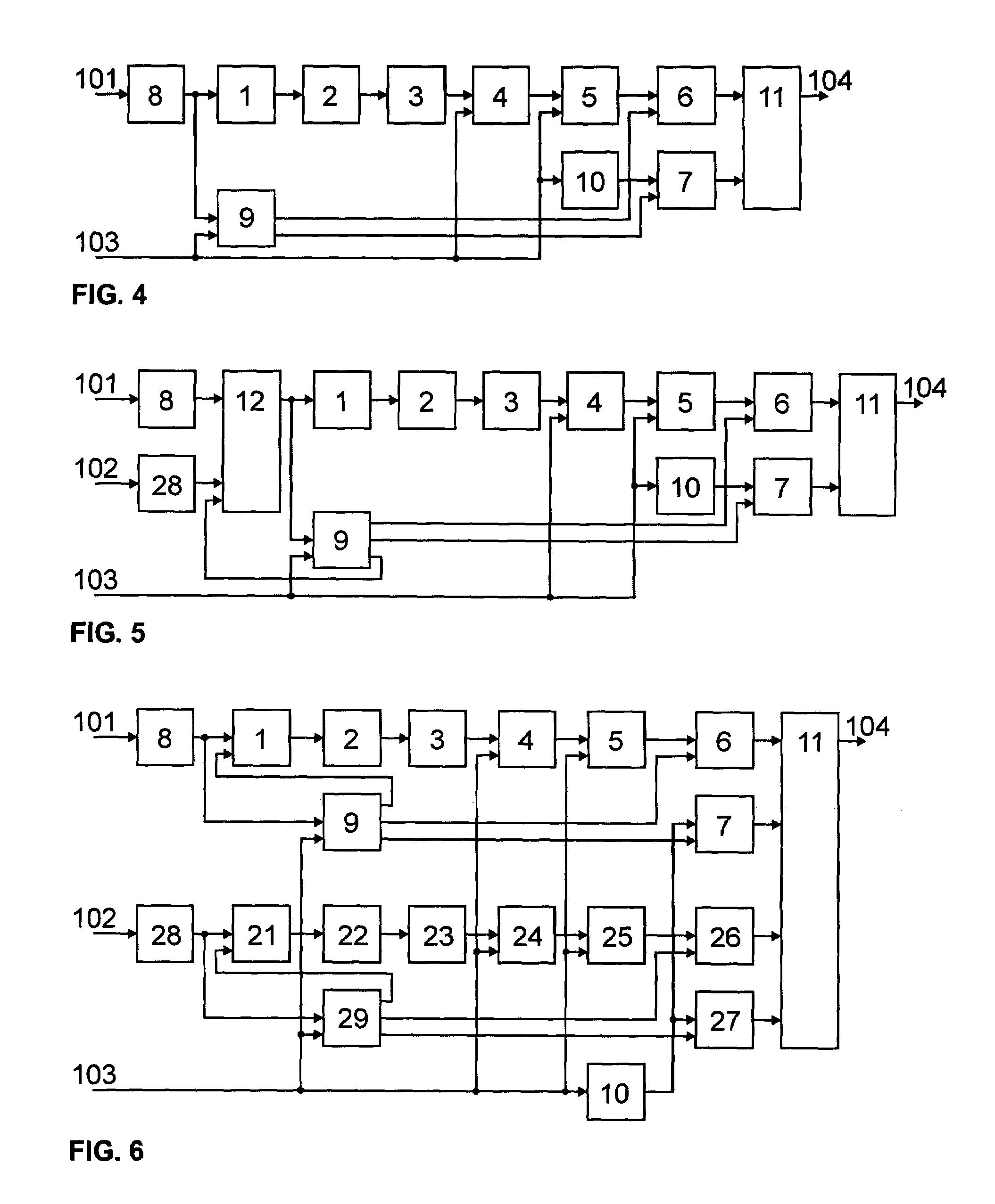
[0026]The devices in the FIG. 1, FIG. 2, and FIG. 3 serve for measurement of time interval between two pulse signals that are identical or similar in shape, but may have different amplitude. They may originate, for instance, from a particle detector, a photo-detector, or a radio receiver detector.

[0027]FIG. 1 shows an example of the first basic configuration of the time interval measurement device. This device is made up of an input 101 of the pulse signal connected through a serial chain, which consists of a filter exciter 1, a surface acoustic wave filter 2, which is a bandpass filter with a finite pulse response, and an amplifier 3, to the analog input of a sampler 4. The output of the sampler 4 is connected to the analog input of an analog-to-digital converter 5, the output of which is connected to the digital input of a sample register 6. The output of the sample register 6 is connected to the first input of the computer 11. The input 101 is further connected through a voltage ...


PUM


Abstract

A device for high accurate measurement of time intervals is based on the conversion of the time interval to a sequence of samples of the response of a surface acoustic wave filter excited at the beginning and at the end of the measured interval. In one of its configurations, the time interval measurement device includes the input of the pulse signal, the filter exciter, the surface acoustic wave filter, the amplifier, the sampler, the analog-to-digital converter, the sample register, the register of sample numbers, the voltage comparator, the control circuit, the sample counter, the computer, the output of the reference clock signal source, and the output of the measured time intervals.

Description

RELATED U.S. APPLICATIONS[0001]Not applicable.STATEMENT REGARDING FEDERALLY SPONSORED RESEARCH OR DEVELOPMENT[0002]Not applicable.REFERENCE TO MICROFICHE APPENDIX[0003]Not applicable.FIELD OF THE INVENTION[0004]The invention deals with a device that allows accurate measurement of time intervals.BACKGROUND OF THE INVENTION[0005]A comprehensive overview of traditional methods of time interval measurement is given, for instance, in the paper: D.I. Porat, “Review of sub-nanosecond time-interval measurements,” IEEE Transactions on Nuclear Science, vol. 20, no. 5, pp. 36–51.[0006]The most widespread method of time interval measurement is based on a counter that counts reference clock pulses. The dynamic range of the measured interval increases almost exponentially with counter length and is practically unlimited. Resolution of this method is given by the reference clock frequency, which is mainly limited by the speed of the digital circuitry in the counter. This is why the resolution of t...

Claims


Application Information

Patent Timeline
Patent Type & Authority Patents(United States)
IPC IPC(8): G04F8/00G04F10/00G04B47/02G04F10/04G04F10/06H03K5/22
CPCG04F10/00
Inventor PANEK, PETR
Owner PANEK PETR
Why Eureka
Try Eureka