Control system, lithographic apparatus, device manufacturing method, and device manufactured thereby

a control system and lithographic technology, applied in the direction of electric controllers, printers, optical radiation measurement, etc., can solve the problems of limiting the speed at which movement to a desired position can be achieved, the current amplifier control system the system speed and accuracy is not suitable for use, so as to improve the accuracy and speed of the movement control system

Inactive Publication Date: 2006-06-13
ASML NETHERLANDS BV
View PDF16 Cites 1 Cited by
  • Summary
  • Abstract
  • Description
  • Claims
  • Application Information

AI Technical Summary

Benefits of technology

[0018]It is an aspect of the present invention to improve the accuracy and speed of a movement control system.
[0022]By providing an additional feedforward control element the accuracy and speed of the response is increased. The system also suffers less phase delay, allowing higher overall performance and stricter design criteria to be applied.
[0023]The limiting factor on the rate of change of current or voltage is now determined by the feedforward value and the power stage of the amplifier, rather than the bandwidth of the current or voltage control loop. Errors are reduced and servo performance increases. Furthermore, the behavior of the system is more predictable and controllable. The system behaves less like a “black box.”
[0027]By calculating one or more of the above feedforward values and adding them to the output of the controller, the performance is increased. The calculation of the feedforward values can be implemented without requiring undue complexity in the controller. The values relating to characteristics of the positioning device may be set once and forgotten, or refined using knowledge of the performance of the individual system in use. The mechanical values used in the feedforward calculations reflect the mechanics of the positioning device. Thus, if a gear ratio is present between the positioning device and the payload the values used in the feedforward calculations will be need to be modified appropriately.
[0029]Optionally, the positioning device may be a multiple phase actuator, and further include a commutator for each phase to adjust the value of the desired current or voltage and the feedforward value. This allows the control system to be easily adapted for use with multiple phase actuators. There is no need to alter the calculation of the feedforward value, the result is adjusted by the commutator.
[0032]Thus, the operation of the lithographic apparatus is improved. The speed of movement of the first and / or second device is increased, allowing greater throughput. Accuracy of the movement is also improved.

Problems solved by technology

These constraints limit the speed at which movement to a desired position can be achieved.
This modified system has improved response but suffers from the constraints of the current amplifier control system, which uses only feedback control.
This places limitations on the speed of movement and accuracy of the system.

Method used


Image

  • Control system, lithographic apparatus, device manufacturing method, and device manufactured thereby
  • Control system, lithographic apparatus, device manufacturing method, and device manufactured thereby
  • Control system, lithographic apparatus, device manufacturing method, and device manufactured thereby

Examples


Embodiment Construction

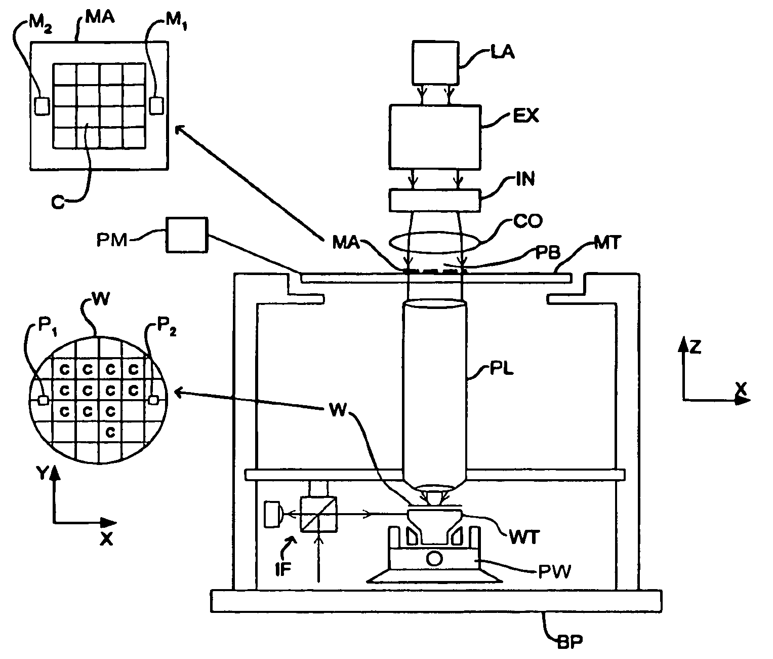
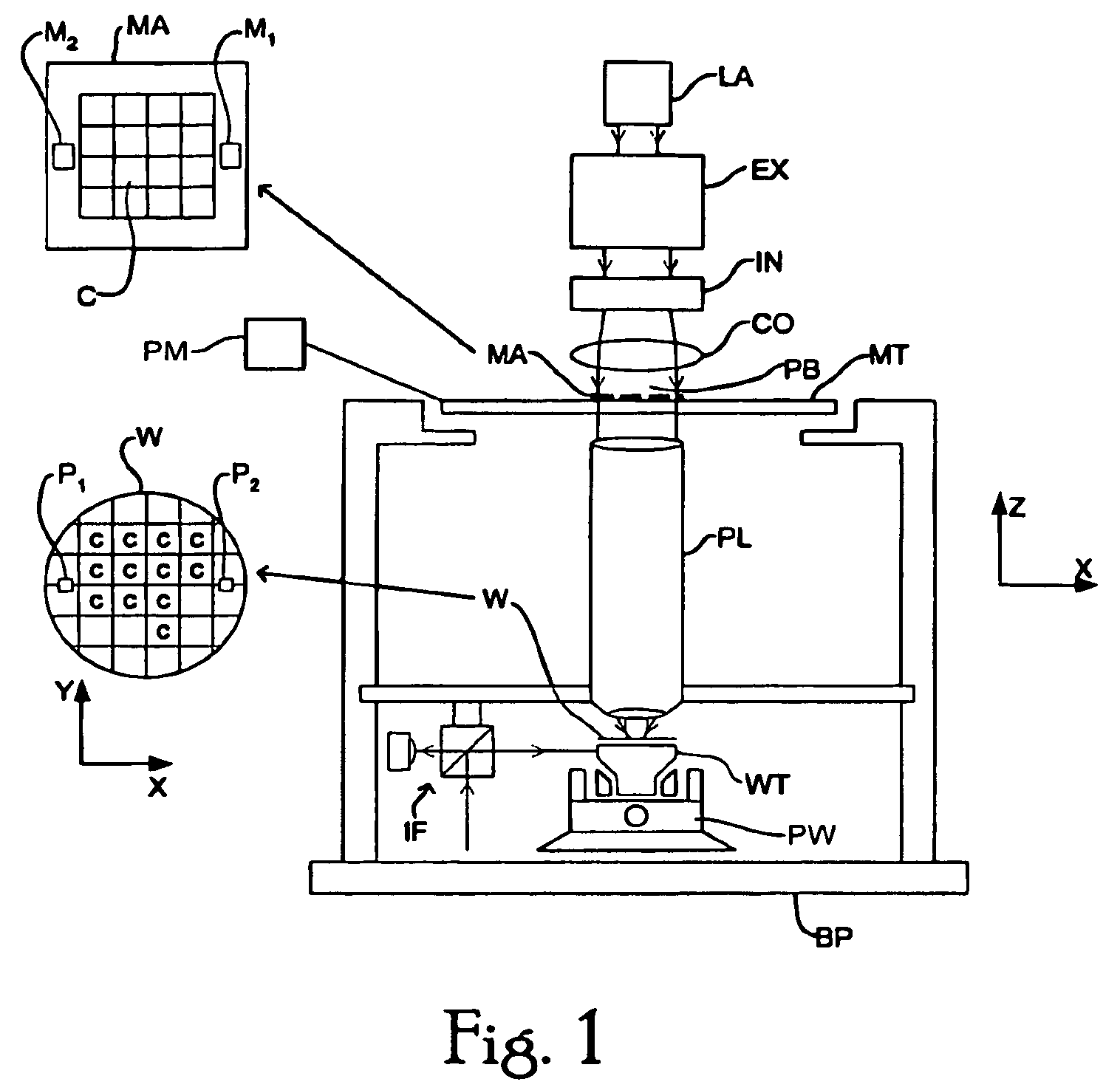
[0045]FIG. 1 schematically depicts a lithographic projection apparatus according to an exemplary embodiment of the present invention. The apparatus includes a radiation system Ex, IL configured to supply a beam PB of radiation (e.g. EUV radiation), which in this case also includes a radiation source LA. A first object table (mask table) MT is provided with a mask holder configured to hold a mask MA (e.g. a reticle) and is connected to a first positioning device that accurately positions the mask with respect to a projection system (“lens”) PL. A second object table (substrate table) WT is provided with a substrate holder configured to hold a substrate W (e.g. a resist-coated silicon wafer) and is connected to a second positioning device PW that accurately positions the substrate with respect to the projection system PL. The projection system (“lens”) PL (e.g. a mirror group) images an irradiated portion of the mask MA onto a target portion C (e.g. including one or more dies) of the ...


PUM

PropertyMeasurementUnit
currentaaaaaaaaaa
wavelengthaaaaaaaaaa

Abstract

A control system for a positioning device includes a controller connected in a feedback loop. The controller calculates a current for supply to the positioning device according to the error between a desired current value and a measured current value. This current is converted to a voltage by an amplifier and further modified by a feedforward voltage calculated using mechanical and electrical characteristics of the positioning device and a desired position and / or desired derivatives of position.

Description

[0001]This application claims priority to European Patent Application 03252965.3, filed May 13, 2003, the contents of which are incorporated by reference.BACKGROUND OF THE INVENTION[0002]1. Field of the Invention[0003]The present invention relates to a control system for a positioning device. The present invention also relates to lithographic apparatus, a device manufacturing method, and a device manufactured thereby.[0004]2. Description of the Related Art[0005]The term “patterning device” as here employed should be broadly interpreted as referring to a device that can be used to endow an incoming radiation beam with a patterned cross-section, corresponding to a pattern that is to be created in a target portion of the substrate. The term “light valve” can also be used in this context. Generally, the pattern will correspond to a particular functional layer in a device being created in the target portion, such as an integrated circuit or other device. An examples of a patterning devic...

Claims


Application Information

Patent Timeline
Patent Type & Authority Patents(United States)
IPC IPC(8): G03B27/58G03B27/62G03B27/42G05B11/36G03F7/20G05B19/19H01L21/027
CPCG03F7/70725G05B19/19G05B2219/37317G05B2219/45028G05B2219/41432G05B2219/41436G05B2219/41426B05B11/0005B05B11/1011B05B11/1042
Inventor DAMS, JOHANNES ADRIANUS ANTONIUS THEODORUS
Owner ASML NETHERLANDS BV
Why Eureka
Try Eureka