Composite material photonic crystal fibres, method of production and its use

a technology of photonic crystal fibres and composite materials, applied in the direction of optical fibers with multi-layer cores/claddings, optical waveguide light guides, instruments, etc., can solve the problems of limited waveguide forming ability of optical crystal fibres, no means for selectively filling holes, and limited waveguide properties of present optical crystal fibre waveguides. , to achieve the effect of reducing the cost of selective filling, and high viscosity

Inactive Publication Date: 2006-06-13
CRYSTAL FIBRE AS
View PDF4 Cites 21 Cited by
  • Summary
  • Abstract
  • Description
  • Claims
  • Application Information

AI Technical Summary

Benefits of technology

[0010]An interesting possibility concerning the development of new material combinations in relation to photonic crystal fibres is described in the patent application U.S. Pat. No. 5,907,647 entitled “Long-period grating switches and devices using them” by Eggleton et al. This invention describes means to obtain an optical switch by employing a long-period fibre grating for switching light between alternative optical paths. The fundamental elements of the device comprise a variable intensity light source, a length of optical waveguide dimensioned for co-propagating light in two distinguishable modes, and a long-period grating in the waveguide for coupling between the two modes. The waveguide is non-linear so that the effective refractive index is a function of intensity, and as a consequence, the coupling produced by the grating is a function of intensity, and different levels of light intensity can switch between the separate modes of the fibre waveguide. In the description by Eggleton et al., examples of the non-linear function of the waveguide such as glass (possibly doped with telluride or selenide) at sufficiently high intensities or other materials such as semiconductors or organic layered materials are mentioned. An advantage of the invention described in U.S. Pat. No. 5,907,647 is that the signal source and the control source can have the same or different wavelengths, and they can pass through the waveguide in the same or different directions. It is, however, a disadvantage that the devices described by the invention of Eggleton et al. require the inclusion of a long-period waveguide grating, and it is described how coupling between modes of the waveguide may be avoided in the absence of the long-period grating.
[0011]Another relevant contribution to the field of photonic crystal fibres (or micro-structured fibres) is described in work by Eggleton and co-workers, see e.g., Optics Express, Vol. 9, No. 13, December 2001, pp. 698–713. In these applications, the micro-structured cladding region is designed to manipulate the propagation of core and leaky cladding modes. The core can incorporate a doped region allowing for the inscription of grating structures, and the air holes can allow for the infusion of active materials yielding novel tuneable hybrid waveguide devices. The resulting hybrid waveguide can be exploited in the design of optical devices such as grating-based filters, tuneable optical filters, tapered fibre devices, and variable optical attenuators. In the tuneable devices described by Eggleton et al., a so-called “grapefruit” micro-structured optical fibre, having six large (about 30–40 micron in diameter) air holes surrounding an inner cladding region of ˜30 microns in diameter. In order to obtain tuneable optical fibre waveguides, Eggleton et al. introduce a polymer (an acrylate monomer mixture) into the six air holes surrounding the core, where after it is UV-cured. The refractive index of the polymer has higher temperature dependence than that of the glass, and since the fundamental mode is not affected by the presence of the air holes, mode guiding in the cladding can be strongly affected by changing the hybrid waveguide temperature by 10–50° C.
[0012]It is a problem that the polymer materials that are immersed in the air holes of the fibre devices described by Eggleton have a relatively high viscosity, and that the air holes, consequently, are relatively large, adding limitations to the waveguide forming ability of the mentioned holes. Optical polymers are, furthermore, often showing losses that are significantly higher in the near infrared wavelength range (around 1300–1600 nm) of particular interest to the optical communications industry. Therefore, it would be relevant to use alternative material combinations and means of additional waveguide modification as described by the present invention. It is a further disadvantage of the disclosures by Eggleton that no means for selectively filling the holes are disclosed.
[0013]Fedotov et al. “Tuning the Photonic Band Gap of Sub-500-nm-Pitch Holey Fibers in the 930–1030-nm Range”, Laser Physics. 2000. V. 10. N. 5. P. 1086 discloses microstructured optical fibres with filled holes that provide tuning of photonic bandgap properties. Zheltikov et al., Journal of Experimental and Theoretical Physics Vol 93(3) pp. 499–509. September 2001 disclose similar fibres as Federov et al.
[0014]It is a disadvantage of the disclosures by Fedotov et al. and Zheltikov et al. that no means for selectively filling the holes are disclosed.
[0015]It is an object of the present invention to provide a new class of optical waveguides, in which the optical waveguiding properties may be actively modified in order to obtain tuneability of the optical fibre devices.

Problems solved by technology

Waveguiding properties of present optical crystal fibre waveguides are limited to properties which can be achieved with silica-based optical waveguides, e.g. wavelength dependent waveguiding properties limited by light attenuation, i.e. light absorption and light scattering.
It is, however, a disadvantage that the devices described by the invention of Eggleton et al. require the inclusion of a long-period waveguide grating, and it is described how coupling between modes of the waveguide may be avoided in the absence of the long-period grating.
It is a problem that the polymer materials that are immersed in the air holes of the fibre devices described by Eggleton have a relatively high viscosity, and that the air holes, consequently, are relatively large, adding limitations to the waveguide forming ability of the mentioned holes.
It is a further disadvantage of the disclosures by Eggleton that no means for selectively filling the holes are disclosed.
It is a disadvantage of the disclosures by Fedotov et al. and Zheltikov et al. that no means for selectively filling the holes are disclosed.

Method used


Image

  • Composite material photonic crystal fibres, method of production and its use
  • Composite material photonic crystal fibres, method of production and its use
  • Composite material photonic crystal fibres, method of production and its use

Examples


Embodiment Construction

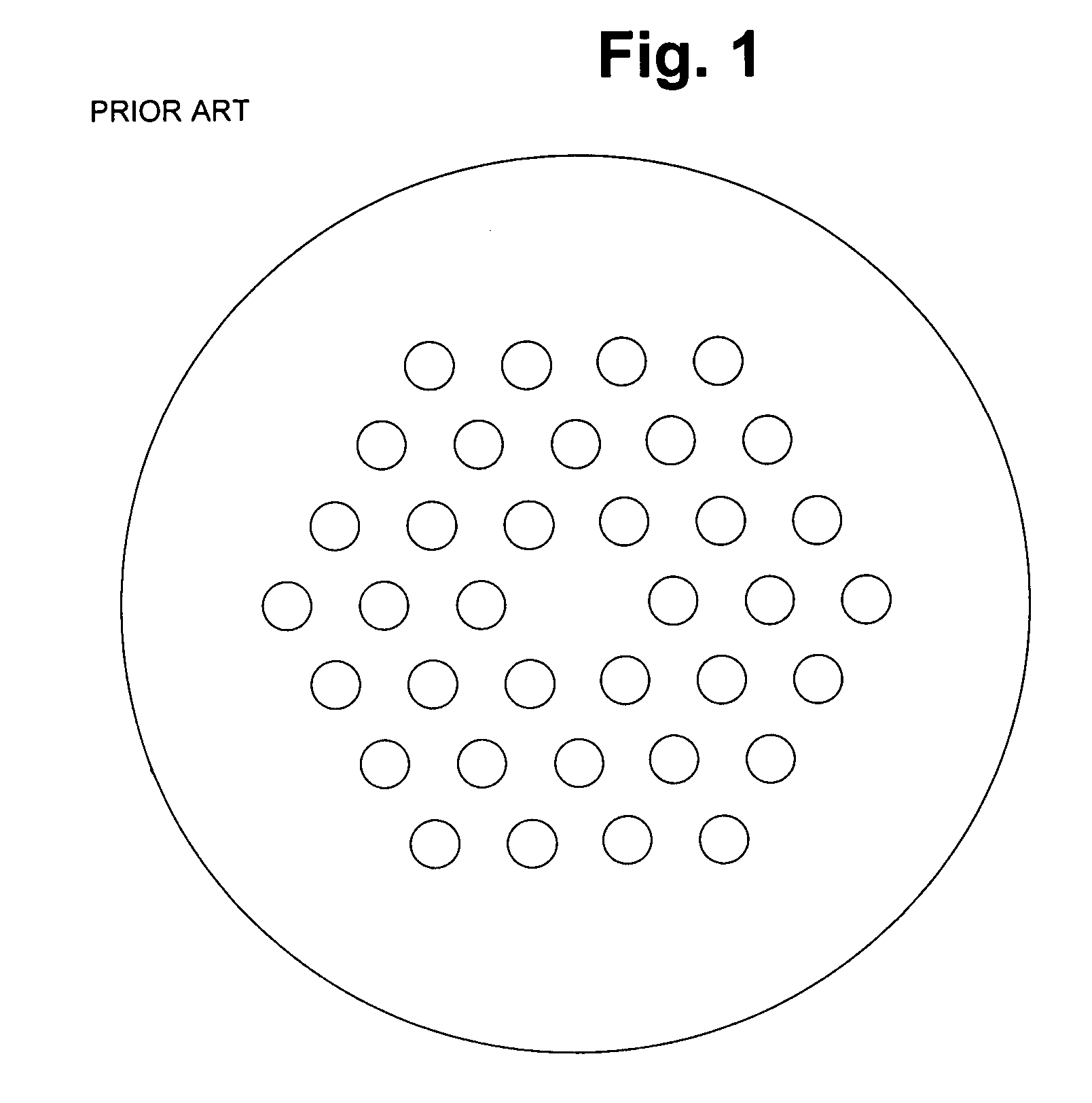
[0166]If we take point of reference in the recent development of optical fibres, a very important development have been the appearance of photonic crystal fibres (PCFs), which typically are manufactured from pure silica with a number of microscopic holes placed in the full length parallel to the axis of the fibre. A schematic illustration of the cross section of a PCF of an often discussed type is shown in FIG. 1. The specific fibre has a solid silica core surrounded by a cladding consisting of air-filled holes placed in a regular triangular pattern according to prior art. This fibre guides light by the principle of modified total internal reflection (M-TIR), which is to some degree similar to the waveguiding principle of standard optical fibres, but has different spectral properties.

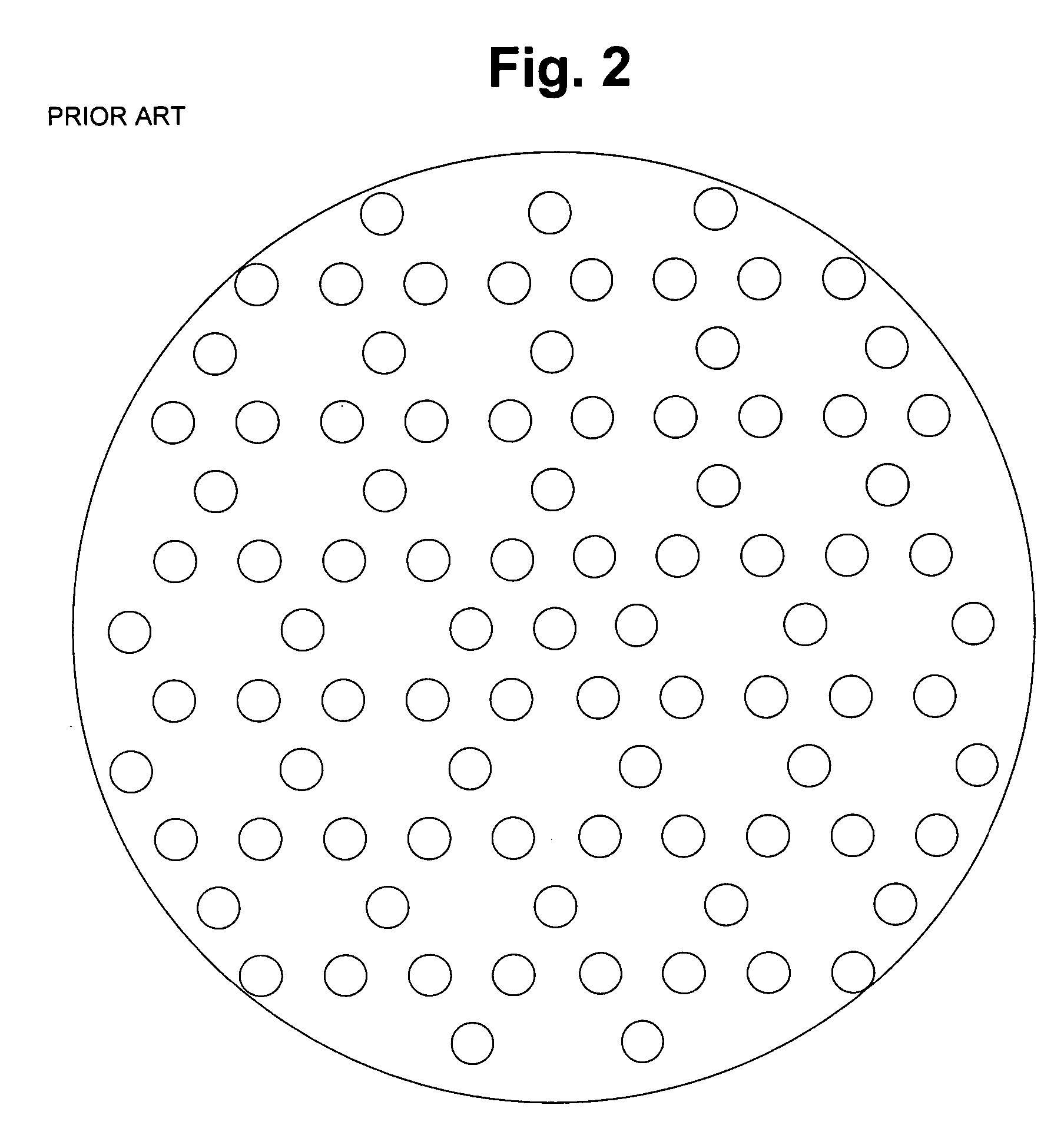
[0167]Another type of PCF according to prior art is illustrated on FIG. 2, which shows a so-called photonic bandgap (PBG) fibre. This type of waveguide operates by a fundamentally different waveguiding ...


PUM

PropertyMeasurementUnit
diameteraaaaaaaaaa
diameteraaaaaaaaaa
near infrared wavelength rangeaaaaaaaaaa

Abstract

An optical fibre for transmission of light at a predetermined wavelength, the fibre having a core region, an inner cladding region and an outer cladding region, the inner cladding region having spaced apart voids, at least some of which are at least partly filled with a fluid substance to modify a refractive index in the cross-section of the fibre. The fluid substance may be introduced by preparing and fixing the fibre ends, identifying the voids to be filled and infusing the fluid therein while masking openings in the remaining voids. By selective heating of parts of the fibre, the location of the fluid substance in the void may be controlled to extend over only a fraction of the length of a void that extends the length by the fibre.

Description

FIELD OF INVENTION[0001]The present invention relates to optical microstructured photonic crystal waveguides, especially for use in optical fibres that provide enhanced waveguide properties through the use of combinations of different materials in microstructured photonic crystal waveguides.BACKGROUND OF THE INVENTION[0002]Within the past few years, a new type of optical fibre that is characterized by a so-called microstructure has received a large interest within the area of optical waveguide research. Optical fibres of this type (which are referred to by several names—e.g., microstructured fibres, photonic crystal fibres, holey fibres, or photonic bandgap fibres) have been described in a number of references, see e.g. Bjarklev, Broeng, and Bjarklev “Photonic crystal fibres”, Kluwer Academic Publishers, 2003. This invention concerns fibres of all types, including those guiding by M-TIR and those fibres guiding by the PBG effect.[0003]Most of the photonic crystal fibres fabricated t...

Claims


Application Information

Patent Timeline
Patent Type & Authority Patents(United States)
IPC IPC(8): G02B6/32G02B6/02
CPCG02B6/02347G02B6/02357G02B6/02376G02B6/02385G02B6/0239G02B6/0238G02B2006/0325
Inventor BJARKLEV, ANDERSSORENSEN, THORKILDBROENG, JES
Owner CRYSTAL FIBRE AS
Why Eureka
Try Eureka