Positive photoresist composition with a polymer including a fluorosulfonamide group and process for its use

a fluorosulfonamide group and composition technology, applied in the field of photoresist composition, can solve the problems of polymer cooh tending to swell and/or quickly dissolve, difficult to achieve slight dissolution in the developer,

Active Publication Date: 2006-06-20
TAIWAN SEMICON MFG CO LTD
View PDF6 Cites 37 Cited by
  • Summary
  • Abstract
  • Description
  • Claims
  • Application Information

AI Technical Summary

Benefits of technology

[0077]While the invention has been described in terms of exemplary embodiments, those skilled in the art will recognize that the present invention may be practiced with modifications within the spirit and scope of the appended claims.

Problems solved by technology
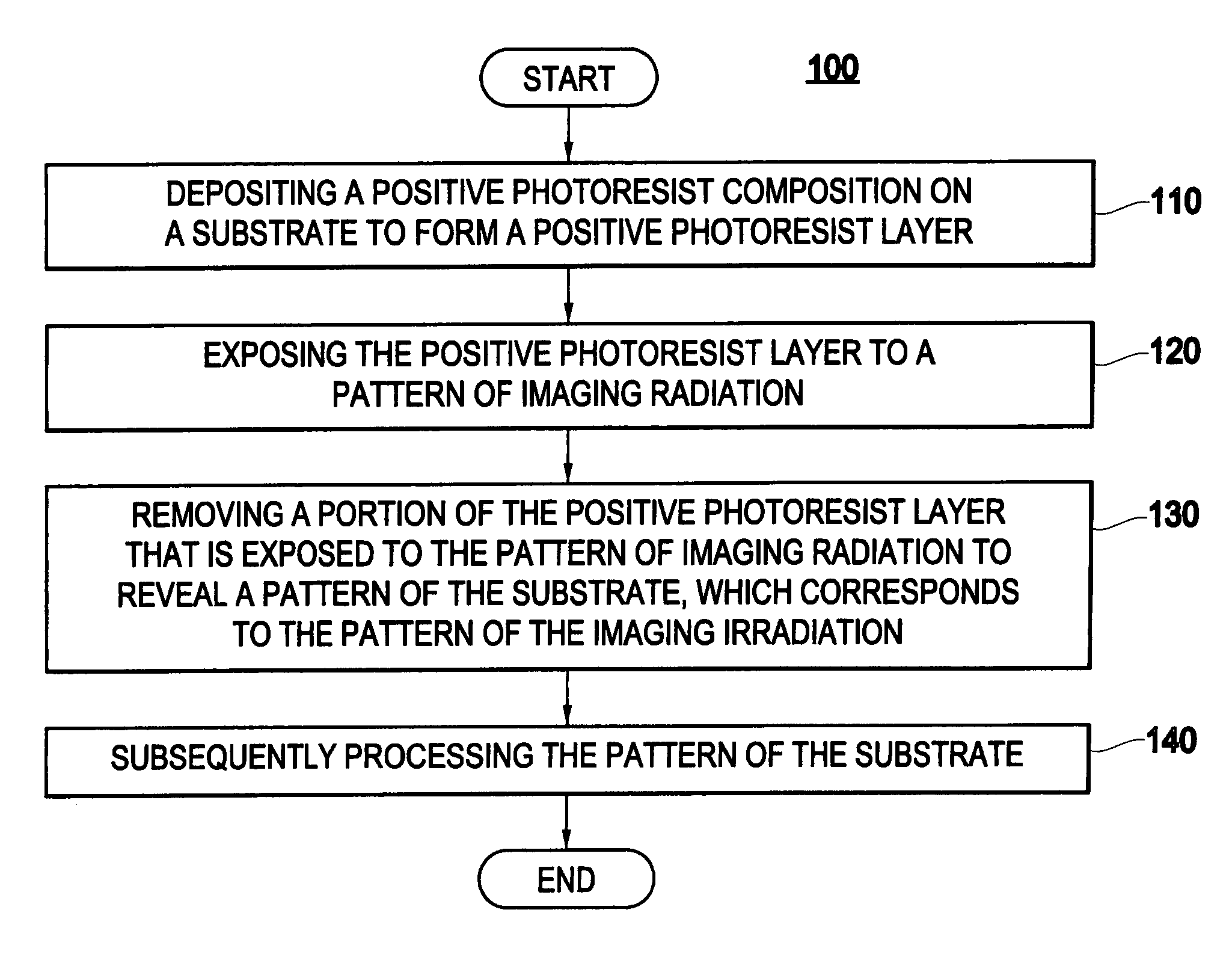
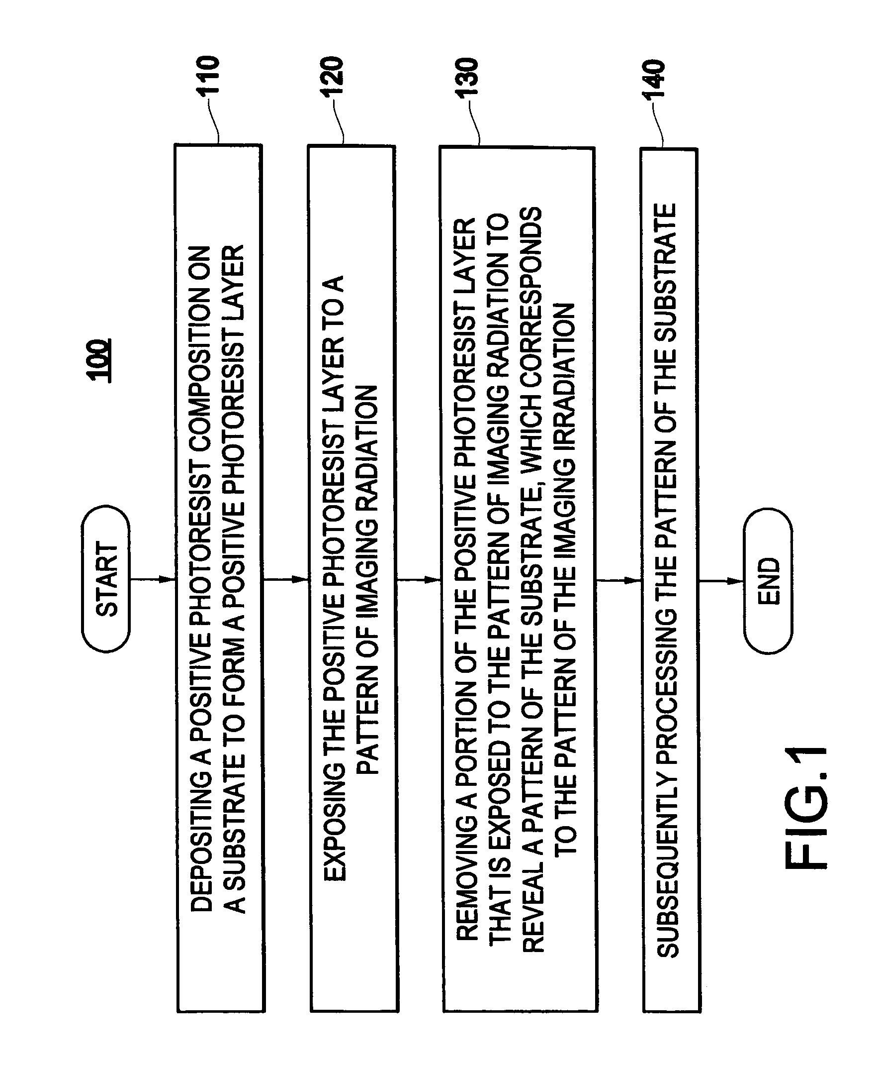
After irradiation, positive photoresists in exposed regions should have a high dissolution rate in the developer, so that they can be easily removed and so subsequent processing is limited to the desired pattern.
Polymers with COOH tend to swell and / or quickly dissolve in an aqueous base developer.
Thus, it is difficult to achieve slight dissolution in the developer before irradiation with polymers having COOH acidic groups.
However, due to the high fluorine content in the HFA group, the etch resistance is often a concern.

Method used


Image

  • Positive photoresist composition with a polymer including a fluorosulfonamide group and process for its use
  • Positive photoresist composition with a polymer including a fluorosulfonamide group and process for its use
  • Positive photoresist composition with a polymer including a fluorosulfonamide group and process for its use

Examples


example 1

Synthesis of Poly(I-co-VIII-co-XVI)

[0073]0.2 g (0.0012 mol) of 2,2′-azobisisobutyronitrile (AlBN) was added to a solution of 1.57 g (0.006 mol) of 2-trifluoromethanesulfonylaminoethyl methacrylate (I), 4.21 g (0.018 mol) of 2-methyl-2-adamantyl methacrylate (VIII), 3.55 g (0.016 mol) of 5-methacryloyloxy-2,6-norbornanecarbolactone (XVI) and 0.081 g (0.0004 mol) dodecanethiol in 28 g of 2-butanone. The solution was deoxygenated by bubbling dry N2 gas through the solution for 0.5 hr and then the solution was allowed to reflux for 12 hr. The reaction mixture of the solution was cooled to room temperature and precipitated in 400 mL of hexanes with rigorous stirring. The resulting white solid was collected by filtration, washed with several portions of hexanes, and dried under vacuum at 60° C. for 20 hr.

example 2

Lithographic Evaluation

[0074]For the purpose of evaluative lithographic experiments, a photoresist formulation containing Poly(I-co-VIII-co-XVI) (Example 1) was prepared by combining the materials set forth below, expressed in part by weight.

[0075]

Propylene glycol monomethyl ether acetate90Poly(I-co-VIII-co-XVI)9.504-(1-Butoxynaphthyl)tetrahydrothiophenium0.475perfluorooctanesulfonate2-Phenylbenzimidazole0.025

[0076]The prepared photoresist formulation was spin-coated for 30 seconds onto an antireflective material (AR40, Shipley Company) layer applied on silicon wafers. The photoresist layer was soft-baked at 130° C. for 60 seconds on a vacuum hot plate to produce a film thickness of about 0.24 μm. The wafers were then exposed to 193 nm radiation (ASML scanner, 0.75 NA). The exposure pattern was an array of lines and spaces of varying dimensions down to 0.09 μm. The exposed wafers were post-exposure baked on a vacuum hot plate at 130° C. for 90 seconds. The wafers were then puddle de...


PUM

PropertyMeasurementUnit
wavelengthaaaaaaaaaa
wavelengthsaaaaaaaaaa
wt. %aaaaaaaaaa

Abstract

A positive photoresist composition comprises a radiations sensitive acid generator, and a polymer that may include a first repeating unit derived from a sulfonamide monomer including a fluorosulfonamide functionality, and a second repeating unit, which may include a pendant acid-labile moiety. The positive photoresist composition may also comprise at least one of a solvent, a quencher, and a surfactant. A patterned photoresist layer, made of the positive photoresist composition, may be formed on a substrate, the positive photoresist layer may be exposed to a pattern of imaging radiation, a portion of the positive photoresist layer that is exposed to the pattern of imaging radiation may be removed to reveal a correspondingly patterned substrate for subsequent processing in the manufacture of a semiconductor device.

Description

BACKGROUND OF THE INVENTION[0001]1. Field of the Invention[0002]The present invention relates to a photoresist composition and, more particularly, to a positive photoresist composition that comprises a polymer comprising a first repeating unit derived from a sulfonamide monomer including a fluorosulfonamide functionality.[0003]2. Description of the Related Art[0004]In the manufacture of semiconductors, the photolithographic process typically projects an ultraviolet (UV) light onto a semiconductor substrate coated with a layer of a photosensitive resist, i.e., a photoresist, through a mask that defines a particular pattern of electronic circuitry. Exposure to UV light, followed by baking, induces a photochemical reaction, which changes the solubility of the exposed regions of the photoresist. Thereafter, an appropriate developer, typically an aqueous base solution, is used to selectively remove the photoresist in the exposed regions or alternatively, in the unexposed regions, to crea...

Claims


Application Information

Patent Timeline
Patent Type & Authority Patents(United States)
IPC IPC(8): G03C1/73G03F7/039C08F220/18C08F220/28C08F220/38C08F232/04G03C1/76G03F7/004G03F7/20H01L21/027
CPCG03F7/0046G03F7/0397Y10S430/111Y10S430/108Y10S430/106
Inventor LI, WENJIEVARANASI, PUSHKARA RAO
Owner TAIWAN SEMICON MFG CO LTD
Why Eureka
Try Eureka