Wire-wound apparatus and high-voltage pulse generating circuit using wire-wound apparatus

a high-voltage pulse and wire-wound technology, which is applied in the direction of transformers/inductances coils/windings/connections, lasers, magnetic cores of inductances, etc., can solve the problem that the cooling medium (insulating oil) in which the reactor is immersed cannot reach between them to fully cool the edges of the core, and the service life is short.

Active Publication Date: 2006-06-20
USHIO DENKI KK
View PDF4 Cites 3 Cited by
  • Summary
  • Abstract
  • Description
  • Claims
  • Application Information

AI Technical Summary

Benefits of technology

[0041]Thus, pressboards between the magnetic core and the electric field easing members become unnecessary, and the wire-wound apparatus can be prevented from having a short service life because of the degradation of the pressboards.
[0042]And, the magnetic core and the electric field easing members are in line contact with each other, and the electric field easing members and the magnetic core are configured not to contact, so that the electric field easing members can be prevented from having an increased temperature due to thermal conduction even if the core is heated, and the pressboards disposed between the electric field easing members and the winding can be prevented from having an increased temperature. Therefore, the pressboard can be prevented from having a shortened service life, and the wire-wound apparatus can be prevented from having a shortened service life because of the degradation of the pressboards.

Problems solved by technology

When the corona discharge occurs, the insulating coating is damaged gradually, resulting in a short circuit in due course.
Generally, a wire-wound apparatus such as a reactor or a step-up transformer generates heat from the core along with the loss of power.
Therefore, the cooling medium (insulating oil) in which the reactor is immersed cannot reach between them to fully cool the edges of the core 1.
Especially, the core 1 has the magnetic alloy strip, which has an insulating coating such as silica formed on its surface, wound on a core tube in an annual ring shape, so that it has poor thermal conduction in the winding direction of the strip.
Therefore, the pressboards 6 have a service life of approximately 3 to 6 months at 160° C. and decompose frequently, resulting in requiring replacement.
As described above, the conventional wire-wound apparatus such as a reactor or a step-up transformer used for a high-voltage pulse generating circuit had a problem that the pressboard is deteriorated and its service life is shortened by heating.

Method used


Image

  • Wire-wound apparatus and high-voltage pulse generating circuit using wire-wound apparatus
  • Wire-wound apparatus and high-voltage pulse generating circuit using wire-wound apparatus
  • Wire-wound apparatus and high-voltage pulse generating circuit using wire-wound apparatus

Examples


first embodiment

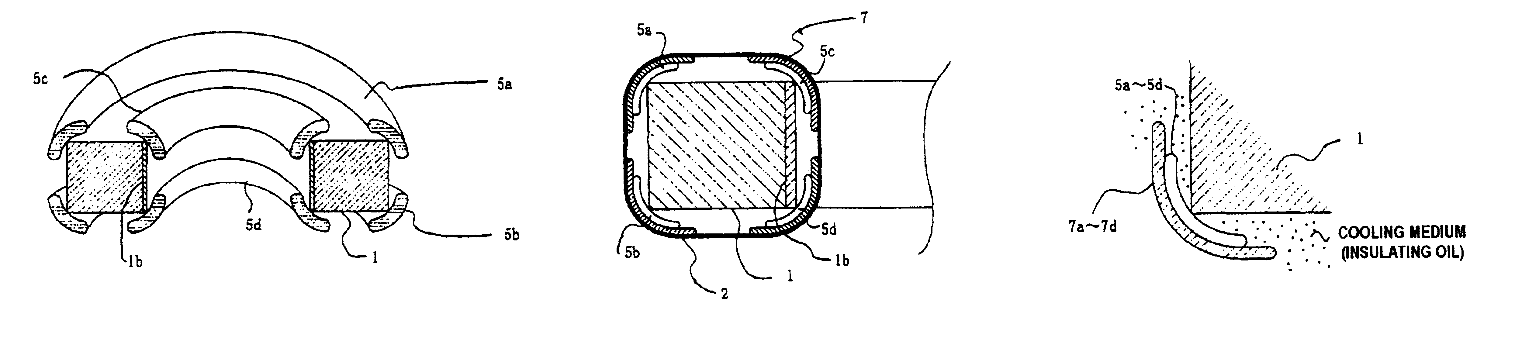
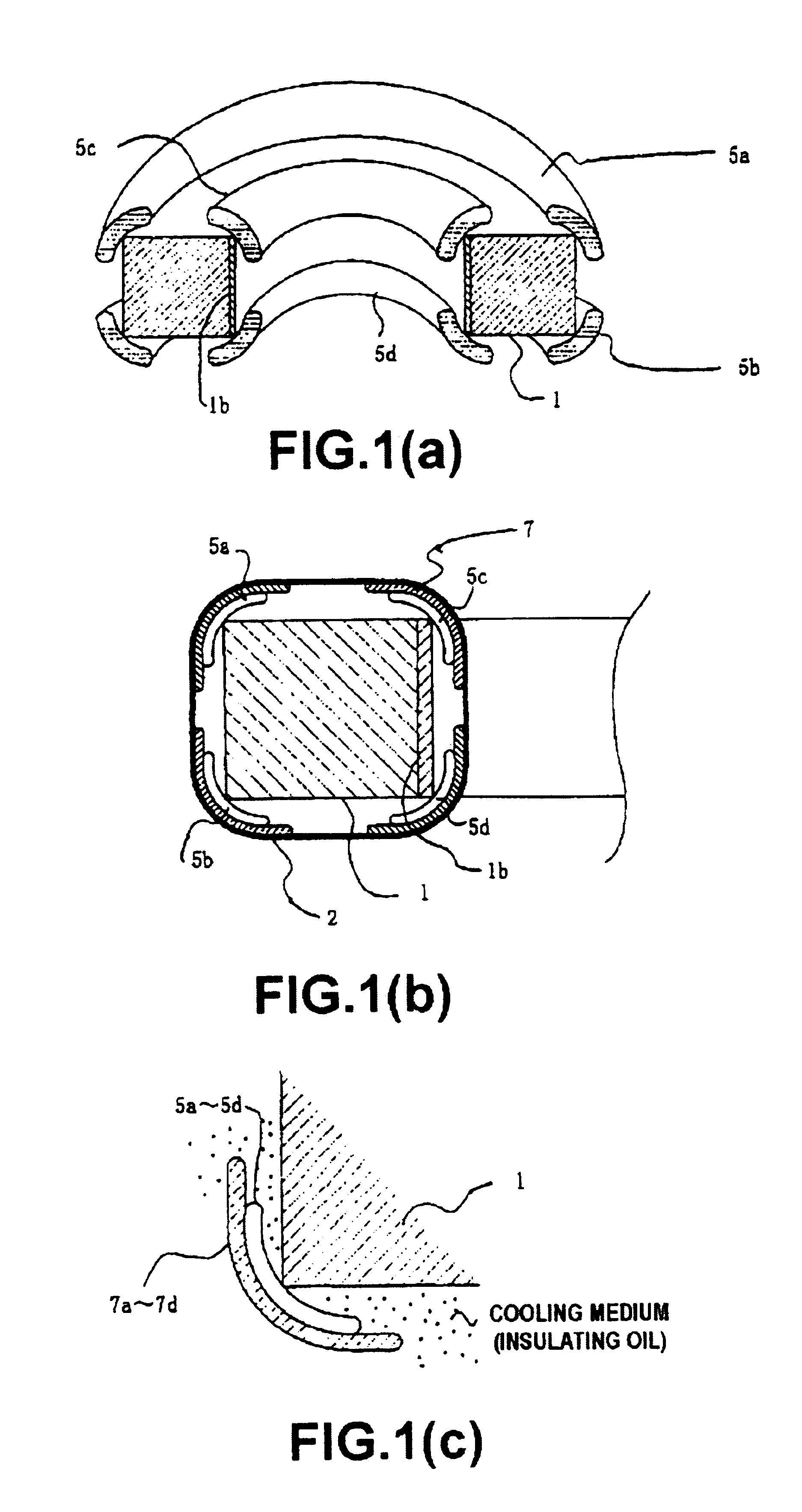
[0062]FIGS. 1(a) to 1(c) are diagrams showing the present invention. FIG. 1(a) is a perspective diagram showing a relationship between a core and corona rings. To make it easy to see, it shows only a semicircular portion of the core, omitting a winding, the pressboards (the pressboards 7 of FIG. 17) enclosing the corona rings and others. And, FIG. 1(b) shows a sectional diagram of the core of this embodiment.

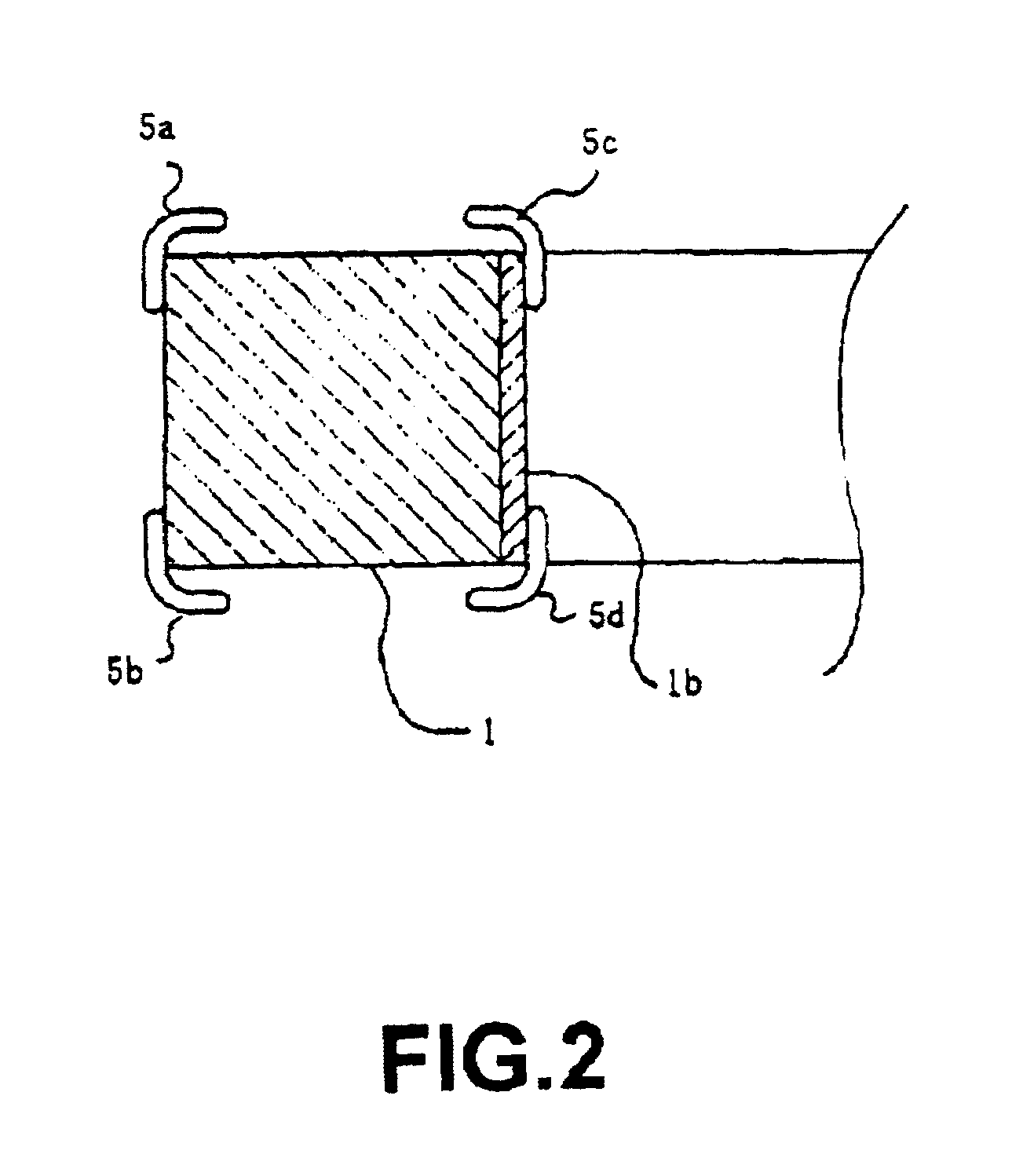
[0063]In this embodiment, corona rings 5a to 5d are disposed along four edges of the core 1 as shown in FIG. 1, the corona rings 5a to 5d have an arc cross section and are in line contact with the edges of the core 1.

[0064]As shown in FIG. 1(b), the pressboards 7 are disposed to enclose the corona rings 5a to 5d, the winding 2 is wound thereon, and the whole is immersed in the insulating oil as described above.

[0065]This embodiment configured as described above does not need to dispose an insulating pressboard (the pressboards 6 shown in FIG. 17) between the core 1 and the coron...

second embodiment

[0075]FIG. 5, FIGS. 6(a) and 6(b), and FIGS. 7(a) and 7(b) are diagrams showing the present invention. This embodiment shows an example of configuration that an annular ring-shape corona ring which is not split is fitted to the annular ring core with a winding omitted from the drawings

[0076]FIG. 5 is a diagram showing the core of this embodiment viewed from above, FIG. 6(a) is a diagram viewing FIG. 5 from direction A, FIG. 6(b) is a sectional diagram taken along fine B—B of FIG. 5, FIG. 7(a) is an enlarged diagram of portion C of FIG. 6(a), and FIG. 7(b) is a sectional diagram taken along line D—D of FIG. 7(a).

[0077]In FIG. 5, FIG. 6 and FIG. 7, 1 denotes a core, and the core 1 is a core having the magnetic alloy strip wound around the annular ring-shape core tube in an annual ring shape. And, a boss 11 is fitted at four points on the periphery of the core 1 to fix the corona rings.

[0078]Reference numerals 5a to 5d denote corona rings, and 7a to 7d denote pressboards. The corona ri...

fourth embodiment

[0087]FIG. 9, FIG. 10 and FIG. 11 show the present invention. This embodiment shows an example configuration of fitting two-split annular ring-shape corona rings to an annular ring core, wherein a winding is omitted.

[0088]FIG. 9 is a diagram of the core of this embodiment viewed from above, FIG. 10(a) is a diagram viewing FIG. 9 from direction F. FIG. 10(b) is a sectional diagram taken along line G—G of FIG. 9(a), and FIG. 11(a) is an enlarged diagram of portion H of FIG. 10(a). FIG. 11(b) shows a sectional diagram taken along line I—I of FIG. 11(a), wherein the upper part diagram shows a state that an arm for coupling the corona rings is not fixed to the boss, and the lower part diagram shows a state that the arm is fixed to the boss.

[0089]In FIG. 9, FIG. 10 and FIG. 11, reference numeral 1 denotes a core. The core 1 is a core having the magnetic alloy strip wound around the annular ring-shape core tube in an annual ring shape as described above, and a boss 11 is fitted at four poi...


PUM

PropertyMeasurementUnit
voltageaaaaaaaaaa
temperatureaaaaaaaaaa
frequencyaaaaaaaaaa

Abstract

Electric field easing members (corona rings) for easing concentration of electric fields caused at edges of a core are disposed between the core and a winding to form a gap so to allow the presence of a cooling medium (insulating oil) between the top and bottom surfaces of the core and the electric field easing members. Thus, pressboards between the core and the electric field easing members become unnecessary, a wire-wound apparatus can be prevented from having a short service life due to the degradation of the pressboards, and the pressboards can be made to have a long service life because the electric field easing members are not heated by thermal conduction from the core.

Description

BACKGROUND OF THE INVENTION[0001]1. Field of the Invention[0002]The present invention relates to a wire-wound apparatus, such as a transformer or a reactor, which has a winding wound around a magnetic core and is used in an insulating cooling medium, and more particularly to a shape of an insulation easing member (hereinafter called as the corona ring) of such wire-wound apparatus.[0003]The present invention can be applied to a saturable reactor, a step-up transformer or the like of a magnetic pulse compression circuit for generating a high-voltage pulse used for a discharge pumped laser, an apparatus for decomposing a compound by an electric discharge or sterilizing, or the like.[0004]2. Description of the Related Art[0005]A discharge pumped laser, a device for decomposing a compound such as dioxin by performing a pulse corona discharge, a pasteurizer for sterilizing food or the like by an electric discharge, or the like has discharging electrodes disposed within a discharge cell (...

Claims


Application Information

Patent Timeline
Patent Type & Authority Patents(United States)
IPC IPC(8): H01S3/03H01S3/097H01F27/34H01S3/00H01F27/24H01F27/26H01F27/28H01F27/32H02M9/04
CPCH01F27/324H01F27/2876H01F27/321
Inventor YAMAMORI, KENJIINOUE, TOYOHARU
Owner USHIO DENKI KK
Why Eureka
Try Eureka