High efficiency optical feedback modulator and method of operation

a high-efficiency, optical feedback technology, applied in the field of fiber optic systems, can solve the problems of large large variability in optical intensity of an optical signal due to the input electrical signal, etc., to achieve the effect of reducing the cost of retrofitting an existing fiber optic system, improving the performance of the fiber optic system, and easy retrofitting into existing fiber optic systems

Inactive Publication Date: 2006-06-20
LOCKHEED MARTIN CORP
View PDF20 Cites 11 Cited by
  • Summary
  • Abstract
  • Description
  • Claims
  • Application Information

AI Technical Summary

Benefits of technology

[0013]Another technical advantage of the present invention is that the present invention can easily be retrofitted into existing fiber optic systems. In particular, the optical feedback system can be easily integrated into existing optical modulators and will immediately improve the performance of the fiber optic system. Accordingly, the costs associated with retrofitting an existing fiber optic system are reduced.
[0014]Another technical advantage of the present invention is

Problems solved by technology

A technical disadvantage is that the variation in optical intensity of an optical signal due to the input electrical signal is relatively small in conventional optical modulators.
Another technical disadvantag

Method used


Image

  • High efficiency optical feedback modulator and method of operation
  • High efficiency optical feedback modulator and method of operation
  • High efficiency optical feedback modulator and method of operation

Examples


Embodiment Construction

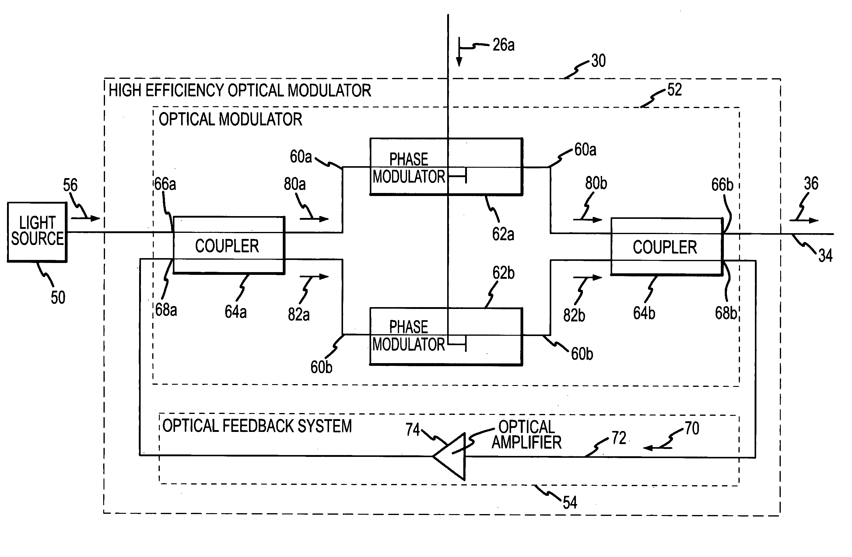
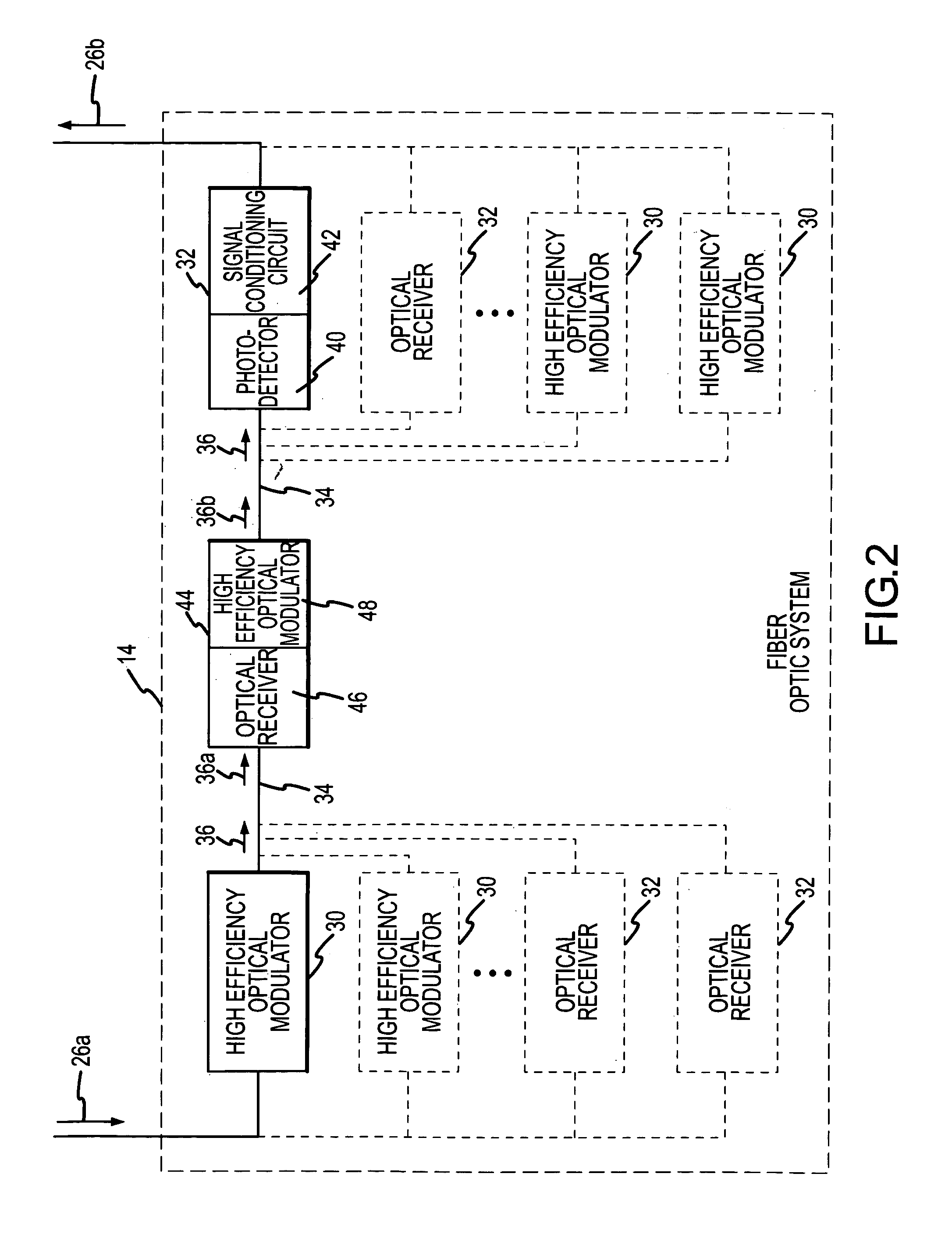
[0022]FIGS. 1 through 5 illustrate a high efficiency optical feedback modulator as used in a fiber optic communication system. As described in greater detail below, the high efficiency optical feedback modulator comprises an optical modulator and an optical feedback system. The optical modulator has at least two optical inputs and at least two optical outputs. The optical feedback system couples one of the optical outputs to one of the optical inputs. As a result, the modulation depth in the optical signal produced by the high efficiency optical feedback modulator is greater than the modulation depth that can be produced by conventional optical modulators.

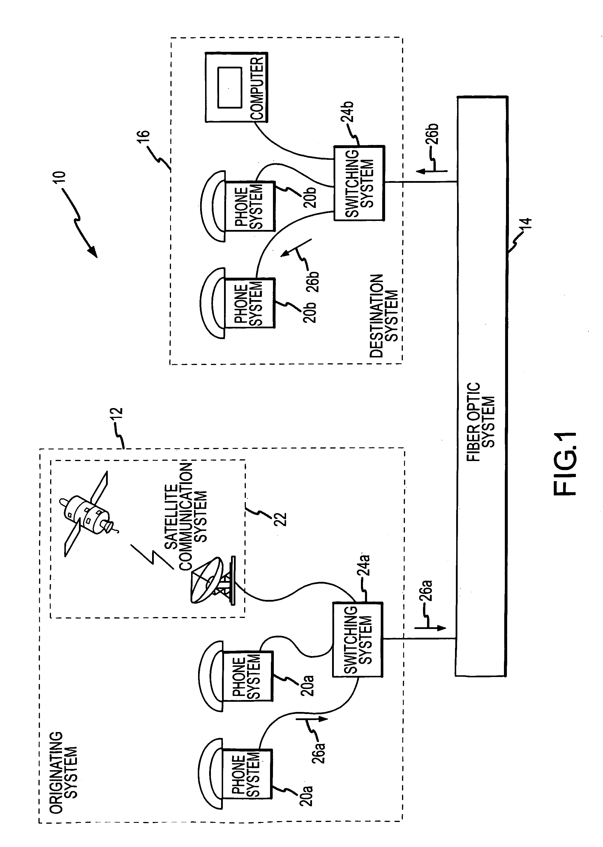
[0023]Although the high efficiency optical feedback modulator is illustrated in terms of a fiber optic communication system, the high efficiency optical feedback modulator may be used in any other suitable fiber optic device or system. For example, the high efficiency optical feedback modulator may be used in satellite communicatio...


PUM


Abstract

A high efficiency optical feedback modulator and method of operation are provided. The high efficiency optical feedback modulator (30) includes an optical modulator (52) and an optical feedback system (54). The optical modulator (52) includes first and second optical inputs (66a, 68a) and first and second optical outputs (66b, 68b). The optical feedback system (54) is coupled between the second optical output (68b) and the second optical input (68a). The second optical input (68a) receives an optical feedback signal (70) from the optical feedback system (54). The first optical input (66a) receives an input light beam (56). The input light beam (56) and the optical feedback signal (70) are modulated with an electronic input signal (26a) to produce a high modulation depth optical signal (36) output from the first optical output (66b). The high efficiency optical feedback modulator (30) achieves a slope efficiency that is an order of magnitude better than conventional optical modulators, corresponding to an RF link gain improvement of 100 times better than conventional optical modulators.

Description

TECHNICAL FIELD OF THE INVENTION[0001]This invention relates generally to the field of fiber optic systems, and more particularly to a high efficiency optical feedback modulator and method of operation.BACKGROUND OF THE INVENTION[0002]Fiber optic systems utilize light transmitted through an optic fiber to communicate information. Fiber optic systems are used in many applications, from the relatively simple, such as a fiber optic telecommunications system, to the complex, such as an optical computer. Fiber optic systems have many advantages over electronic systems, including, greater information carrying capacity and smaller size, as well as being resistant to electromagnetic interference and relatively inexpensive to fabricate and install.[0003]To illustrate the general operation of a fiber optic system, the operation of a fiber optic communication system is described. Fiber optic communication systems operate by modulating a received electronic signal, such as a phone call, into an...

Claims


Application Information

Patent Timeline
IPC IPC(8): H04B10/02
CPCH04B10/505H04B10/5057H04B10/5053
Inventor JELKS, EDWARD CHRISTIAN
Owner LOCKHEED MARTIN CORP
Why Eureka
Try Eureka