Interrogation method for passive sensor monitoring system

a passive sensor and interrogation method technology, applied in transmission systems, tyre measurements, frequency analysis, etc., can solve the problems of inability to measure the beat frequency, unreliability, cumbersomeness, etc., and achieve the effect of high efficiency of resonator excitation and high measurement accuracy

Inactive Publication Date: 2006-06-20
TRANSENSE TECH
View PDF28 Cites 22 Cited by
  • Summary
  • Abstract
  • Description
  • Claims
  • Application Information

AI Technical Summary

Benefits of technology

[0009]The object of the present invention is to provide an interrogation method that preserves the advantages of Fourier analysis and at the same time provides high efficiency of resonator excitation and high accuracy of measurements.

Problems solved by technology

As a result, the interrogation system requires relatively wide bandwidth of 10 MHz or even more, which is not available in license-free industrial-scientific-medical (ISM) bands below 1 GHz.
Measuring the beat frequency is impossible in this case.
This technique is more appropriate for a single resonator and becomes too cumbersome and unreliable in the case of three resonators, especially if their frequencies are close to each other.2. The resonators are excited by RF pulses in turn.
However, if it is less than 10 times the bandwidth (which is the case in ISM band), then more than one resonator will be excited by the RF pulse causing parasitic frequency modulation in the sensor response and drastically reducing accuracy of measurement.3. All three resonators are excited in one go.
Bearing in mind that the peak power of the interrogation pulse is limited in ISM band (usually it is not more than 10 mW) it is clear that spreading the spectrum of the pulse reduces efficiency of resonator excitation.
It adversely affects signal-to-noise ratio (SNR) and hence accuracy of measurements.

Method used


Image

  • Interrogation method for passive sensor monitoring system
  • Interrogation method for passive sensor monitoring system
  • Interrogation method for passive sensor monitoring system

Examples


Embodiment Construction

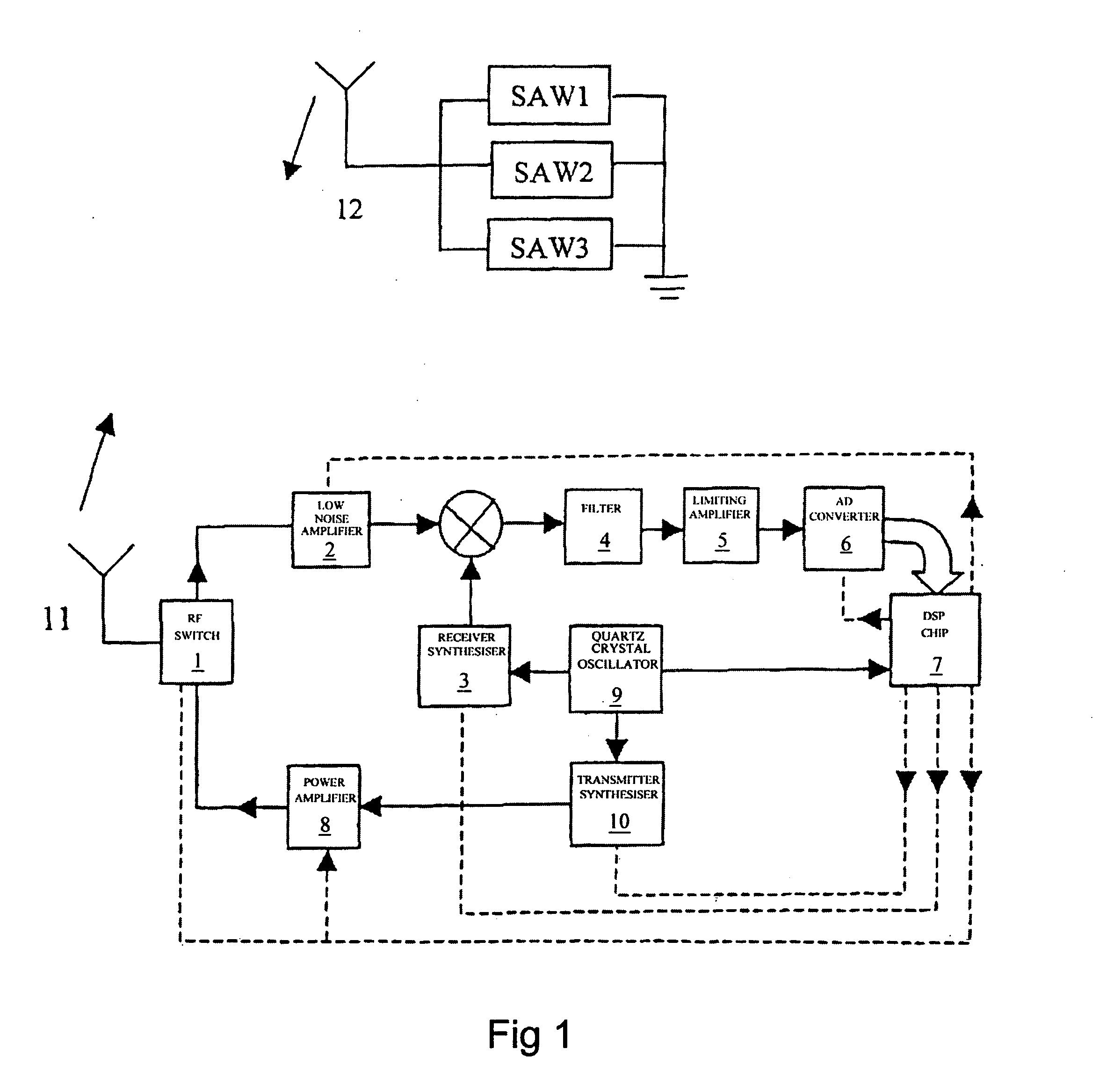
[0018]Referring firstly to FIG. 1, the present invention is particularly applicable to a system for monitoring the temperature and pressure in a vehicle tire. However, it is to be understood that the invention is not limited to this application and may be applied to other circumstances where pressure and temperature are to be monitored, or indeed to other circumstances where a plurality of other perimeters are to be measured by a passive sensor system. The preferred embodiment of the present invention includes three surface acoustic wave devices SAW1, SAW2 and SAW3 which are connected to a common antenna 12. While the use of SAW devices is preferred as a means of generating signals indicative of the sensed condition, it is to be understood that the invention is not limited to such devices and other passive sensors capable of providing appropriate indications by means of resonant frequency may be employed.

[0019]In the particular preferred application of the present invention (vehicle...


PUM

PropertyMeasurementUnit
peak poweraaaaaaaaaa
frequencyaaaaaaaaaa
interrogation frequenciesaaaaaaaaaa

Abstract

A method of determining the frequency of a plurality of resonant devices (for example three SAW devices) includes determining optimal interrogation frequencies for each of the devices, the optimal interrogation frequencies having maximum power spectral densities, accumulating a plurality of responses for each sensor, performing discrete Fourier transforms on the sampling results to estimate the three resonant frequencies, and averaging the results of the Fourier transforms to provide an indication of resonant frequencies. The averaging step may include the calculation of a standard deviation and the rejection of any results which fall more than a pre-determined multiple of the standard deviation from the average frequency result. The frequency determined by the method may be employed to calculate the pressure and temperature of the sensor devices. The sensor devices may be located in a vehicle tire.

Description

TECHNICAL FIELD OF THE INVENTION[0001]This invention relates to a method for interrogating sensor systems based on wirelessly interrogated passive sensory-transponders as used, for example, for measuring pressure and temperature of air in vehicle tires. More specifically, the preferred embodiment of the invention provides a passive sensor interrogation algorithm which allows high accuracy of measurement of pressure and temperature.DESCRIPTION OF RELATED ART[0002]A number of solutions for the problem of a wireless interrogation of passive pressure and temperature sensors are known in the prior art. The sensors utilize either one-port delay lines or one-port resonators, preferably based on SAW technology, although other approaches are also possible (bulk acoustic wave devices or dielectric resonators, for instance). The use of the delay lines [see F. Schmidt and G. Scholl, Wireless SAW identification and sensor systems. In a book “Advances in Surface Acoustic Wave Technology, Systems ...

Claims


Application Information

Patent Timeline
Patent Type & Authority Patents(United States)
IPC IPC(8): G01R23/16G01L17/00B60C23/04G01K13/08G01L9/00G06K19/067G08B21/00G08C17/02
CPCB60C23/0433G06K19/0675G06K19/0672
Inventor KALININ, VICTOR ALEXANDROVICHBECKLEY, JOHN PETERBOWN, GEORGE E.
Owner TRANSENSE TECH
Why Eureka
Try Eureka