System and method to customize bond programs compensating integrated circuit bonder variability

a technology of integrated circuit bonding and program customization, applied in the field of semiconductor devices and electronic systems, can solve the problems of reducing the accuracy of pattern recognition system reference placement, wire bonding techniques, and the inability of the bond head to place the bonds, so as to reduce the error rate of operation program

Inactive Publication Date: 2006-06-27
TEXAS INSTR INC
View PDF11 Cites 4 Cited by
  • Summary
  • Abstract
  • Description
  • Claims
  • Application Information

AI Technical Summary

Benefits of technology

[0034]Beyond the electronics realm, the computerized system and method of this invention can be generally applied to reduce operational program errors on slave machines prepared to work on action sites of slave objects, when a master machine and a master object, having a structure similar to the slave object, are available.

Problems solved by technology

Without knowing accurately the target bonding locations, the bond head cannot place the bonds as expected.
Large differences in intensity settings can reduce the ability of the pattern recognition system to locate the references accurately.
Problems in wire bonding techniques arise in part from the technology trends to increase the number of leads in a given package and to make IC chip packages smaller.
For instance, even small bond placement errors may result in device loss.
Further, a x-y pair might have a global positioning error because of an error in the orthogonality between them; or the tables may exhibit a range of hysteresis errors.
These variations become even more threatening as common device programs are shared due to quality enforcement and economic reasons.
The current systems have difficulties in achieving this.Large variations in illumination settings can lead to variations of the images as seen by the optics and the camera.
These variations may affect the ability of the pattern recognition system in locating the homes and bond locations accurately.The current systems cannot handle x-y table inconsistencies.
For small pad / fine pitch bonding, a small error in ball placement can cause the ball to be partially off the pad.Human error during regeneration of alignment program: Ball placement is greatly affected by the accuracy of the alignment program.
There are many steps to this regeneration process and thus there are many chances for human error.Time spent performing alignment regeneration: Whenever a device is to be bonded, a human operator typically has to spend a finite amount of time to perform an alignment regeneration.

Method used


Image

  • System and method to customize bond programs compensating integrated circuit bonder variability
  • System and method to customize bond programs compensating integrated circuit bonder variability
  • System and method to customize bond programs compensating integrated circuit bonder variability

Examples


Embodiment Construction

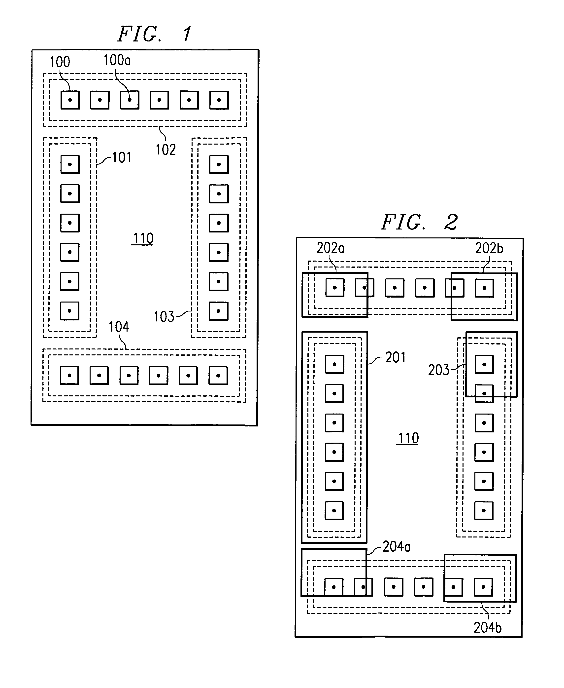
[0046]In order to eliminate variability of the automated bonding machines (“bonders”), which may depend on the specific apparatus or may be time-dependent, the invention uses the approach to group a small set of bond pad locations into “segments” during the device program “teaching”. As examples, FIGS. 1 and 2 illustrate the approach and the solution to problems in assembling semiconductor chip 110 caused by machine-related errors in bonding operation. As illustrated in FIG. 1, a plurality of bond pads 100 lined up along one of the x or y axes may be grouped as a segment. All or some of the bond pads may be grouped into different segments, such as the four segments 101, 102, 103, and 104 in FIG. 1, each containing six bond pads. Within the small stretch covered by the segment, it may be assumed that the bonding tables behave linearly (polynomially). (In the ideal assembly case illustrated, all bonds 100a attached to pads 100 are located in the center of the pad areas.)

[0047]Each seg...


PUM


Abstract

A computerized system and method for customizing bond programs in order to compensate first for variabilities in an integrated circuit (IC) “slave” bonder, and second to any irregularities in a “slave” circuit positioned on the slave bonder for attaching connecting bonds onto the IC bond pads. According to the invention, a “master” segmentator groups the bond pads of a “master” circuit on a master bonder into segments and stores the reference data related to these segments in a master file. Next, a slave regenerator, coupled to the master file, regenerates the master reference data so that variable characteristics of the slave bonder are defined and adaptively compensated. Finally, a slave corrector, coupled to the salve regenerator, corrects the bond program for the slave circuit on the adaptively compensated slave bonder. The slave bonder attaches the connecting bonds based on the computed correct bond locations.

Description

[0001]This application claims priority under 35 USC § 119 based upon Provisional Patent Application No. 60,204,997. filed May 16 / 2000.FIELD OF THE INVENTION[0002]The present invention is related in general to the field of semiconductor devices and electronic systems and more specifically to bond program customization and operation of computer-controlled bonding machines used in integrated circuit assembly.DESCRIPTION OF THE RELATED ART[0003]In integrated circuit (IC) assembly, an IC chip is typically mounted on a leadframe and electrically connected to it by metallic segments. Commonly, the chip assembly is encapsulated in a protective package (for instance, ceramic package, or plastic package using molding process). Typically, the IC chip has a plurality of bond pads, which are often positioned around the chip perimeter; these bond pads have predetermined bonding area and spacing (bond pad pitch). The leadframe usually has a plurality of narrow “inner” leads for attachment to the s...

Claims


Application Information

Patent Timeline
Patent Type & Authority Patents(United States)
IPC IPC(8): G06F19/00G05B19/408
CPCG05B19/4083G05B2219/45033G05B2219/36048G05B2219/36046
Inventor BON, DAVID J.KODURI, SREENIVASAN K.
Owner TEXAS INSTR INC
Why Eureka
Try Eureka